H.14
SEL-351A Relay Instruction Manual Date Code 20080213
Distributed Network Protocol
Data Map
Data Map
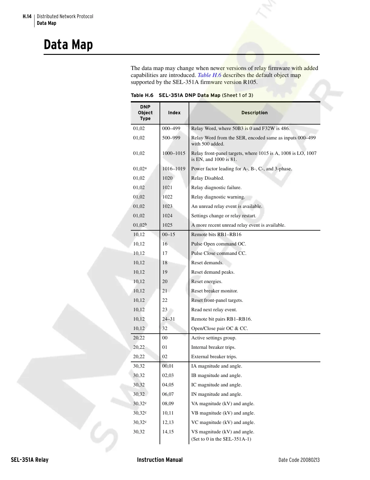
The data map may change when newer versions of relay firmware with added
capabilities are introduced. Table H.6 describes the default object map
supported by the SEL-351A firmware version R105.
Table H.6 SEL-351A DNP Data Map (Sheet 1 of 3)
DNP
Object
Type
Index Description
01,02 000–499 Relay Word, where 50B3 is 0 and F32W is 486.
01,02 500–999 Relay Word from the SER, encoded same as inputs 000–499
with 500 added.
01,02 1000–1015 Relay front-panel targets, where 1015 is A, 1008 is LO, 1007
is EN, and 1000 is 81.
01,02
a
1016–1019 Power factor leading for A-, B-, C-, and 3-phase.
01,02 1020 Relay Disabled.
01,02 1021 Relay diagnostic failure.
01,02 1022 Relay diagnostic warning.
01,02 1023 An unread relay event is available.
01,02 1024 Settings change or relay restart.
01,02
b
1025 A more recent unread relay event is available.
10,12 00–15 Remote bits RB1–RB16
10,12 16 Pulse Open command OC.
10,12 17 Pulse Close command CC.
10,12 18 Reset demands.
10,12 19 Reset demand peaks.
10,12 20 Reset energies.
10,12 21 Reset breaker monitor.
10,12 22 Reset front-panel targets.
10,12 23 Read next relay event.
10,12 24–31 Remote bit pairs RB1–RB16.
10,12 32 Open/Close pair OC & CC.
20,22 00 Active settings group.
20,22 01 Internal breaker trips.
20,22 02 External breaker trips.
30,32 00,01 IA magnitude and angle.
30,32 02,03 IB magnitude and angle.
30,32 04,05 IC magnitude and angle.
30,32 06,07 IN magnitude and angle.
30,32
c
08,09 VA magnitude (kV) and angle.
30,32
c
10,11 VB magnitude (kV) and angle.
30,32
c
12,13 VC magnitude (kV) and angle.
30,32 14,15 VS magnitude (kV) and angle.
(Set to 0 in the SEL-351A-1)
Courtesy of NationalSwitchgear.com