2.32
SEL-351A Relay Instruction Manual Date Code 20080213
Installation
SEL-351A AC/DC Connection Diagrams for Various Applications
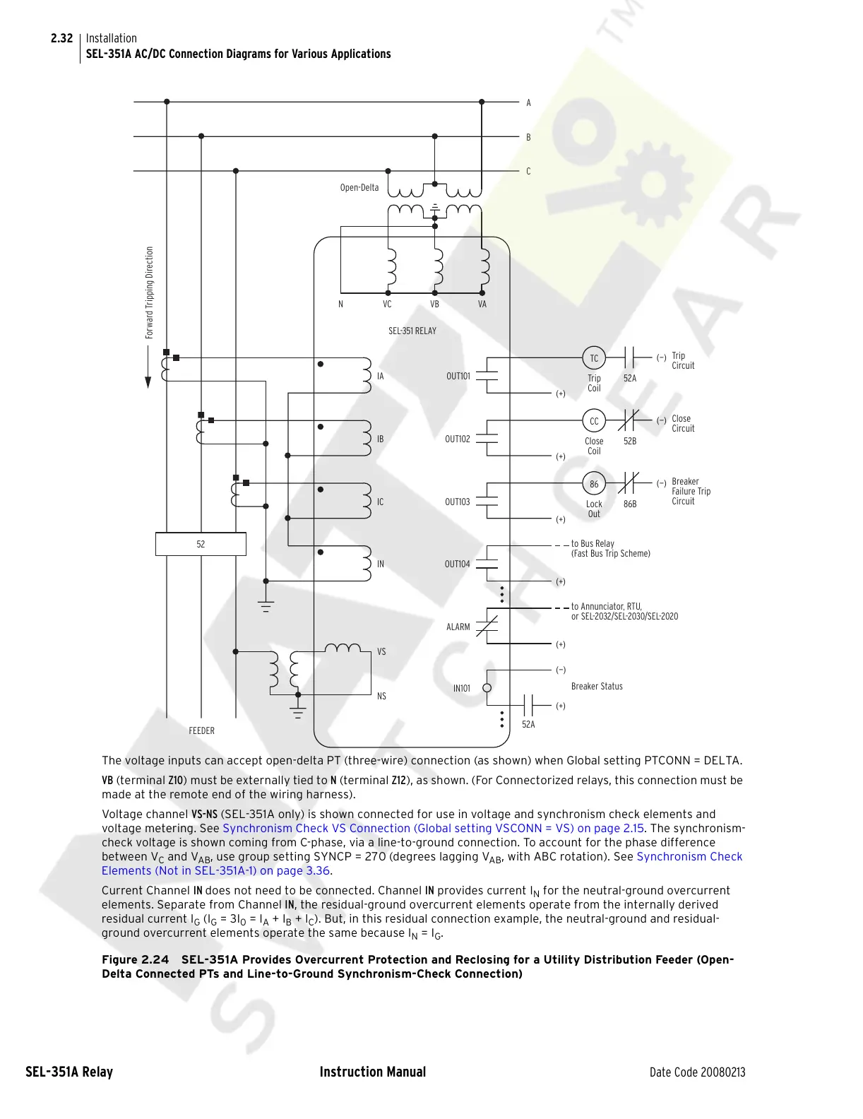
The voltage inputs can accept open-delta PT (three-wire) connection (as shown) when Global setting PTCONN = DELTA.
VB (terminal Z10) must be externally tied to N (terminal Z12), as shown. (For Connectorized relays, this connection must be
made at the remote end of the wiring harness).
Voltage channel VS-NS (SEL-351A only) is shown connected for use in voltage and synchronism check elements and
voltage metering. See Synchronism Check VS Connection (Global setting VSCONN = VS) on page 2.15. The synchronism-
check voltage is shown coming from C-phase, via a line-to-ground connection. To account for the phase difference
between V
C
and V
AB
, use group setting SYNCP = 270 (degrees lagging V
AB
, with ABC rotation). See Synchronism Check
Elements (Not in SEL-351A-1) on page 3.36.
Current Channel IN does not need to be connected. Channel IN provides current I
N
for the neutral-ground overcurrent
elements. Separate from Channel IN, the residual-ground overcurrent elements operate from the internally derived
residual current I
G
(I
G
= 3I
0
= I
A
+ I
B
+ I
C
). But, in this residual connection example, the neutral-ground and residual-
ground overcurrent elements operate the same because I
N
= I
G
.
Figure 2.24 SEL-351A Provides Overcurrent Protection and Reclosing for a Utility Distribution Feeder (Open-
Delta Connected PTs and Line-to-Ground Synchronism-Check Connection)
TC
Trip
Coil
52A
(+)
(—)
Trip
Circuit
IA
C
B
A
SEL-351 RELAY
OUT101
Forward Tripping Direction
CC
Close
Coil
52B
(+)
(—)
Close
Circuit
IB
OUT102
86
Lock
Out
86B
(+)
(—)
Breaker
Failure Trip
Circuit
IC
OUT103
IN
VS
NS
FEEDER
52
(+)
OUT104
(+)
52A
to Annunciator, RTU,
or SEL-2032/SEL-2030/SEL-2020
to Bus Relay
(Fast Bus Trip Scheme)
ALARM
(+)
(—)
Breaker Status
IN101
NVCVB
VA
Open-Delta
Courtesy of NationalSwitchgear.com