4.27
Date Code 20080213 Instruction Manual SEL-351A Relay
Loss-of-Potential, Load Encroachment, and Directional Element Logic
Directional Control for Neutral-Ground and Residual-Ground Overcurrent Elements (Not in SEL-351A-1)
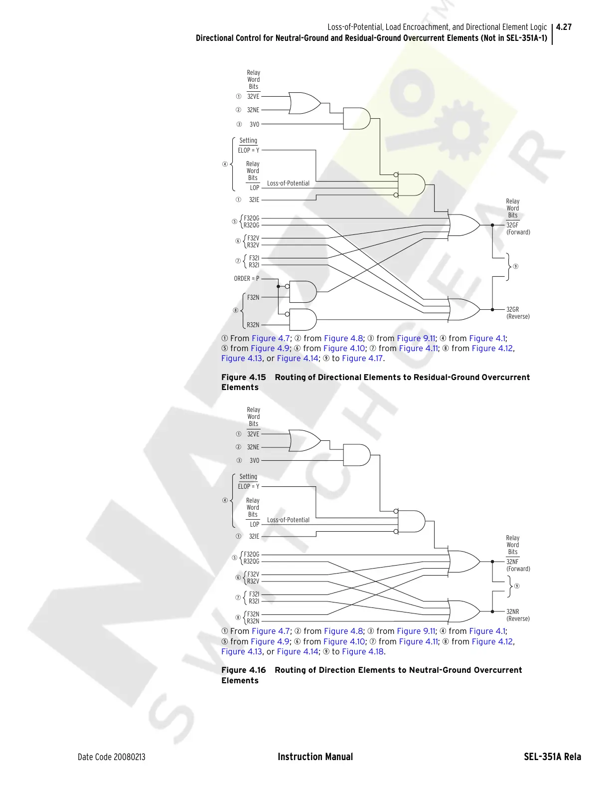
q From Figure 4.7; w from Figure 4.8; e from Figure 9.11; r from Figure 4.1;
t from Figure 4.9; y from Figure 4.10; u from Figure 4.11; i from Figure 4.12,
Figure 4.13, or Figure 4.14; o to Figure 4.17.
Figure 4.15 Routing of Directional Elements to Residual-Ground Overcurrent
Elements
q From Figure 4.7; w from Figure 4.8; e from Figure 9.11; r from Figure 4.1;
t from Figure 4.9; y from Figure 4.10; u from Figure 4.11; i from Figure 4.12,
Figure 4.13, or Figure 4.14; o to Figure 4.18.
Figure 4.16 Routing of Direction Elements to Neutral-Ground Overcurrent
Elements
LOP
Relay
Word
Bits
q
32VE
w
32NE
F32QG
R32QG
e
3V0
q
32IE
Relay
Word
Bits
32GF
(Forward)
32GR
(Reverse)
Relay
Word
Bits
Setting
ELOP = Y
r
i
o
t
F32V
R32V
y
Loss-of-Potential
F32I
R32I
ORDER = P
F32N
R32N
u
LOP
Relay
Word
Bits
q
32VE
w
32NE
F32QG
R32QG
e
3V0
q 32IE
Relay
Word
Bits
32NF
(Forward)
32NR
(Reverse)
Relay
Word
Bits
Setting
ELOP = Y
r
o
t
F32V
R32V
y
Loss-of-Potential
F32I
R32I
u
F32N
R32N
i
Courtesy of NationalSwitchgear.com