4.51
Date Code 20080213 Instruction Manual SEL-351A Relay
Loss-of-Potential, Load Encroachment, and Directional Element Logic
Directional Control Settings (Not in SEL-351A-1)
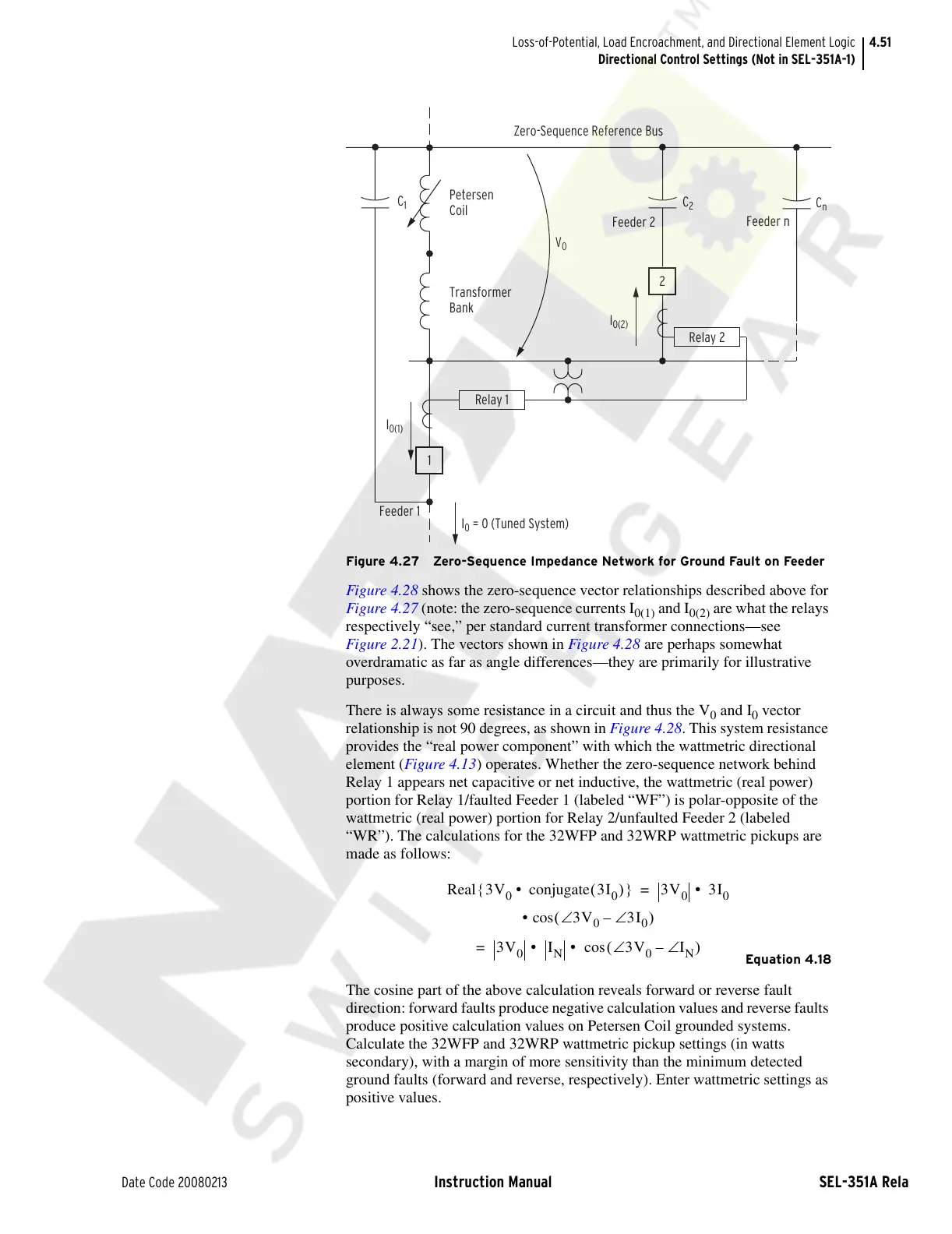
Figure 4.27 Zero-Sequence Impedance Network for Ground Fault on Feeder
Figure 4.28 shows the zero-sequence vector relationships described above for
Figure 4.27 (note: the zero-sequence currents I
0(1)
and I
0(2)
are what the relays
respectively “see,” per standard current transformer connections—see
Figure 2.21). The vectors shown in Figure 4.28 are perhaps somewhat
overdramatic as far as angle differences—they are primarily for illustrative
purposes.
There is always some resistance in a circuit and thus the V
0
and I
0
vector
relationship is not 90 degrees, as shown in Figure 4.28. This system resistance
provides the “real power component” with which the wattmetric directional
element (Figure 4.13) operates. Whether the zero-sequence network behind
Relay 1 appears net capacitive or net inductive, the wattmetric (real power)
portion for Relay 1/faulted Feeder 1 (labeled “WF”) is polar-opposite of the
wattmetric (real power) portion for Relay 2/unfaulted Feeder 2 (labeled
“WR”). The calculations for the 32WFP and 32WRP wattmetric pickups are
made as follows:
Equation 4.18
The cosine part of the above calculation reveals forward or reverse fault
direction: forward faults produce negative calculation values and reverse faults
produce positive calculation values on Petersen Coil grounded systems.
Calculate the 32WFP and 32WRP wattmetric pickup settings (in watts
secondary), with a margin of more sensitivity than the minimum detected
ground faults (forward and reverse, respectively). Enter wattmetric settings as
positive values.
Petersen
Coil
Transformer
Bank
C
1
C
2
C
n
Feeder 2
Feeder n
Relay 1
V
0
2
Relay 2
I
0(2)
1
I
0(1)
Feeder 1
I
0
= 0 (Tuned System)
Zero-Sequence Reference Bus
Real 3V
0
conjugate 3I
0
()• {}3V
0
3I
0
• =
• cos 3V
0
3I
0
∠–∠()
3V
0
I
N
3V
0
∠ I
N
∠–()cos• • =
Courtesy of NationalSwitchgear.com

 Loading...