1.2
SEL-351A Relay Instruction Manual Date Code 20080213
Introduction and Specifications
SEL-351A Models
SEL-351A Models
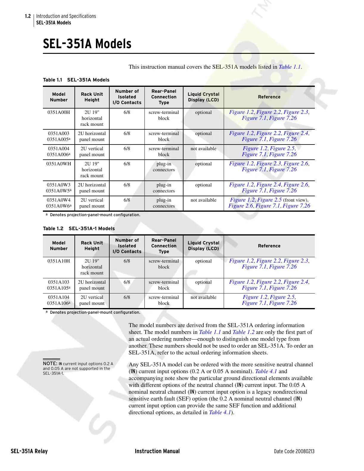
This instruction manual covers the SEL-351A models listed in Table 1.1.
The model numbers are derived from the SEL-351A ordering information
sheet. The model numbers in Table 1.1 and Table 1 .2 are only the first part of
an actual ordering number—enough to distinguish one model type from
another. These numbers should not be used to order an SEL-351A. To order an
SEL-351A, refer to the actual ordering information sheets.
NOTE: IN current input options 0.2 A
and 0.05 A are not supported in the
SEL-351A-1.
Any SEL-351A model can be ordered with the more sensitive neutral channel
(IN) current input options (0.2 A or 0.05 A nominal). Table 4.1 and
accompanying note show the particular ground directional elements available
with different options of the neutral channel (IN) current input. The 0.05 A
nominal neutral channel (IN) current input option is a legacy nondirectional
sensitive earth fault (SEF) option (the 0.2 A nominal neutral channel (IN)
current input option can provide the same SEF function and additional
directional options, as detailed in Table 4.1).
Table 1.1 SEL-351A Models
Model
Number
Rack Unit
Height
Number of
Isolated
I/O Contacts
Rear-Panel
Connection
Typ e
Liquid Crystal
Display (LCD)
Reference
0351A00H 2U 19"
horizontal
rack mount
6/8 screw-terminal
block
optional Figure 1.2, Figure 2.2, Figure 2.3,
Figure 7.1, Figure 7.26
0351A003
0351A005
a
2U horizontal
panel mount
6/8 screw-terminal
block
optional Figure 1.2, Figure 2.2, Figure 2.4,
Figure 7.1, Figure 7.26
0351A004
0351A006
a
2U vertical
panel mount
6/8 screw-terminal
block
not available Figure 1.2, Figure 2.5,
Figure 7.1, Figure 7.26
0351A0WH 2U 19"
horizontal
rack mount
6/8 plug-in
connectors
optional Figure 1.2, Figure 2.3, Figure 2.6,
Figure 7.1, Figure 7.26
0351A0W3
0351A0W5
a
2U horizontal
panel mount
6/8 plug-in
connectors
optional Figure 1.2, Figure 2.4, Figure 2.6,
Figure 7.1, Figure 7.26
0351A0W4
0351A0W6
a
2U vertical
panel mount
6/8 plug-in
connectors
not available Figure 1.2, Figure 2.5 (front view),
Figure 2.6, Figure 7.1, Figure 7.26
a
Denotes projection-panel-mount configuration.
Table 1.2 SEL-351A-1 Models
Model
Number
Rack Unit
Height
Number of
Isolated
I/O Contacts
Rear-Panel
Connection
Typ e
Liquid Crystal
Display (LCD)
Reference
0351A10H 2U 19"
horizontal
rack mount
6/8 screw-terminal
block
optional Figure 1.2, Figure 2.2, Figure 2.3,
Figure 7.1, Figure 7.26
0351A103
0351A105
a
2U horizontal
panel mount
6/8 screw-terminal
block
optional Figure 1.2, Figure 2.2, Figure 2.4,
Figure 7.1, Figure 7.26
0351A104
0351A106
a
2U vertical
panel mount
6/8 screw-terminal
block
not available Figure 1.2, Figure 2.5,
Figure 7.1, Figure 7.26
a
Denotes projection-panel-mount configuration.
Courtesy of NationalSwitchgear.com