5.10
SEL-351A Relay Instruction Manual Date Code 20080213
Trip and Target Logic
Front-Panel Target LEDS
Front-Panel Target LEDS
Target LEDs numbered 2 through 13 in Tabl e 5 .1 are updated and then latched
for every new assertion (rising edge) of the TRIP Relay Word bit. The TRIP
Relay Word bit is the output of the trip logic (see Figure 5.1).
Further target LED information follows. Refer also to Figure 2.3–Figure 2.5
for the placement of the target LEDs on the front panel.
Additional Target LED
Information
TRIP Target LED
The TRIP target LED illuminates at the rising edge of trip (the new assertion of
the TRIP Relay Word bit).
The TRIP target LED is especially helpful in providing front-panel indication
for tripping that does not involve overcurrent or frequency elements. If the trip
is not an overcurrent or frequency element generated trip, none of the target
LEDs numbered 3 through 13 in Table 5.1 illuminate, but the TRIP target LED
still illuminates. Thus, tripping via the front-panel local control (local bits),
serial port (remote bits or OPEN command), or voltage elements is indicated
only by the illumination of the TRIP target LED.
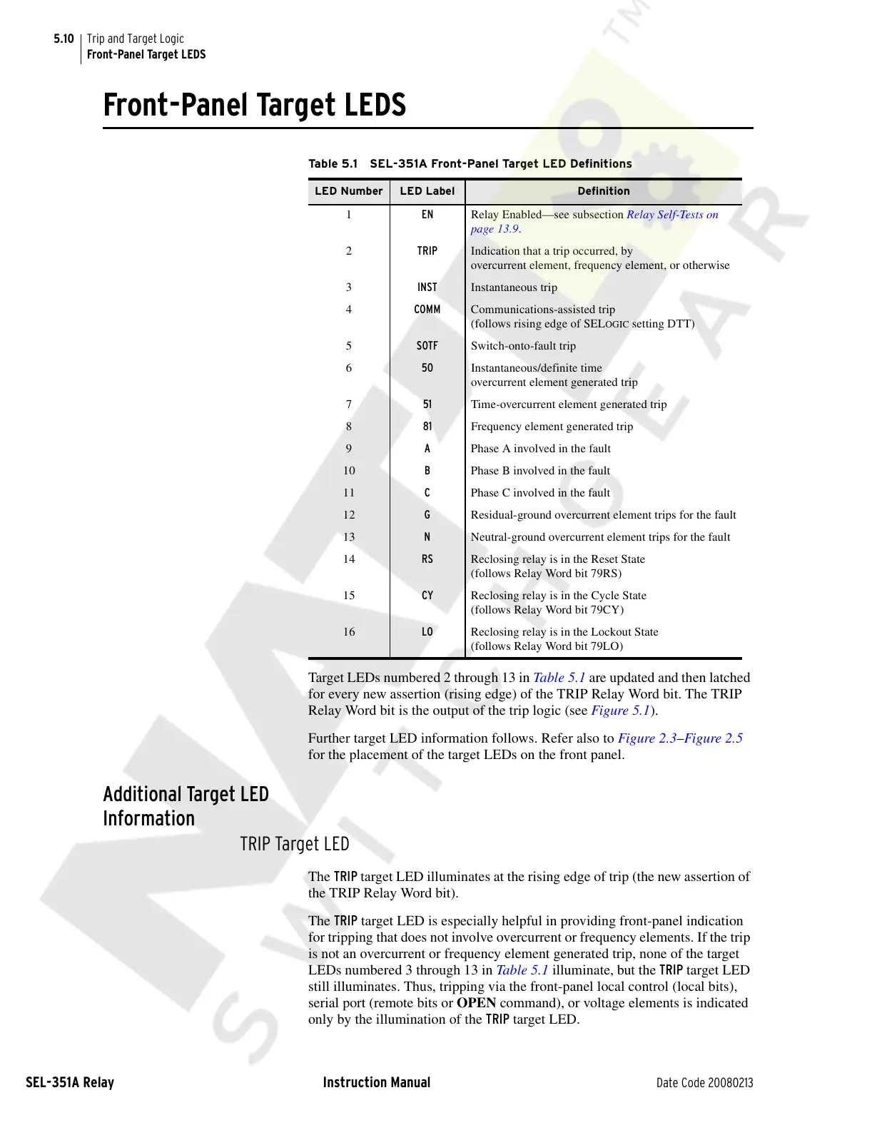
Table 5.1 SEL-351A Front-Panel Target LED Definitions
LED Number LED Label Definition
1 EN Relay Enabled—see subsection Relay Self-Tests on
page 13.9.
2 TRIP Indication that a trip occurred, by
overcurrent element, frequency element, or otherwise
3 INST Instantaneous trip
4 COMM Communications-assisted trip
(follows rising edge of SEL
OGIC setting DTT)
5 SOTF Switch-onto-fault trip
6 50 Instantaneous/definite time
overcurrent element generated trip
7 51 Time-overcurrent element generated trip
8 81 Frequency element generated trip
9 A Phase A involved in the fault
10 B Phase B involved in the fault
11 C Phase C involved in the fault
12 G Residual-ground overcurrent element trips for the fault
13 N Neutral-ground overcurrent element trips for the fault
14 RS Reclosing relay is in the Reset State
(follows Relay Word bit 79RS)
15 CY Reclosing relay is in the Cycle State
(follows Relay Word bit 79CY)
16 LO Reclosing relay is in the Lockout State
(follows Relay Word bit 79LO)
Courtesy of NationalSwitchgear.com

 Loading...