4.39
Date Code 20080213 Instruction Manual SEL-351A Relay
Loss-of-Potential, Load Encroachment, and Directional Element Logic
Directional Control Settings (Not in SEL-351A-1)
Not all these directional control settings (set automatically or by the user) are
used in every application. The following are particular directional control
settings that are hidden/not made for particular conditions:
Settings
DIR1—Level 1 Overcurrent Element Direction Setting
DIR2—Level 2 Overcurrent Element Direction Setting
DIR3—Level 3 Overcurrent Element Direction Setting
DIR4—Level 4 Overcurrent Element Direction Setting
Setting Range:
➤ F = Direction Forward
➤ R = Direction Reverse
➤ N = Nondirectional
Table 4.4 shows the overcurrent elements that are controlled by each level
direction setting. Note in Table 4.4 that all the time-overcurrent elements
(51_T elements) are controlled by the DIR1 level direction setting.
Figure 4.17, Figure 4.18, Figure 4.23, and Figure 4.24 show the logic
implementation of the control listed in Table 4.4.
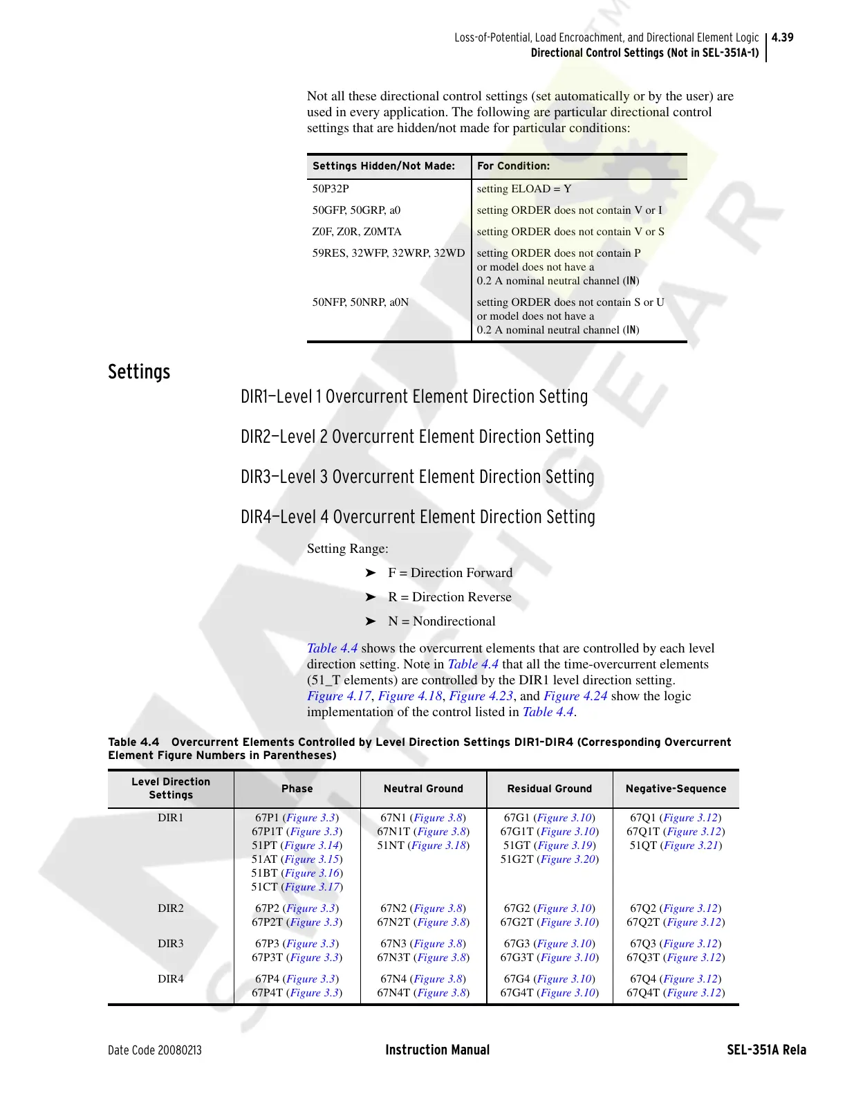
Settings Hidden/Not Made: For Condition:
50P32P setting ELOAD = Y
50GFP, 50GRP, a0 setting ORDER does not contain V or I
Z0F, Z0R, Z0MTA setting ORDER does not contain V or S
59RES, 32WFP, 32WRP, 32WD setting ORDER does not contain P
or model does not have a
0.2 A nominal neutral channel (IN)
50NFP, 50NRP, a0N setting ORDER does not contain S or U
or model does not have a
0.2 A nominal neutral channel (IN)
Table 4.4 Overcurrent Elements Controlled by Level Direction Settings DIR1–DIR4 (Corresponding Overcurrent
Element Figure Numbers in Parentheses)
Level Direction
Settings
Phase Neutral Ground Residual Ground Negative-Sequence
DIR1 67P1 (Figure 3.3)
67P1T (Figure 3.3)
51PT (Figure 3.14)
51AT (Figure 3.15)
51BT (Figure 3.16)
51CT (Figure 3.17)
67N1 (Figure 3.8)
67N1T (Figure 3.8)
51NT (Figure 3.18)
67G1 (Figure 3.10)
67G1T (Figure 3.10)
51GT (Figure 3.19)
51G2T (Figure 3.20)
67Q1 (Figure 3.12)
67Q1T (Figure 3.12)
51QT (Figure 3.21)
DIR2 67P2 (Figure 3.3)
67P2T (Figure 3.3)
67N2 (Figure 3.8)
67N2T (Figure 3.8)
67G2 (Figure 3.10)
67G2T (Figure 3.10)
67Q2 (Figure 3.12)
67Q2T (Figure 3.12)
DIR3 67P3 (Figure 3.3)
67P3T (Figure 3.3)
67N3 (Figure 3.8)
67N3T (Figure 3.8)
67G3 (Figure 3.10)
67G3T (Figure 3.10)
67Q3 (Figure 3.12)
67Q3T (Figure 3.12)
DIR4 67P4 (Figure 3.3)
67P4T (Figure 3.3
)
67N4 (Figure 3.8)
67N4T (Figure 3.8)
67G4 (Figure 3.10)
67G4T (Figure 3.10)
67Q4 (Figure 3.12)
67Q4T (Figure 3.12)
Courtesy of NationalSwitchgear.com