7.20
SEL-351A Relay Instruction Manual Date Code 20080213
Inputs, Outputs, Timers, and Other Control Logic
Multiple Setting Groups
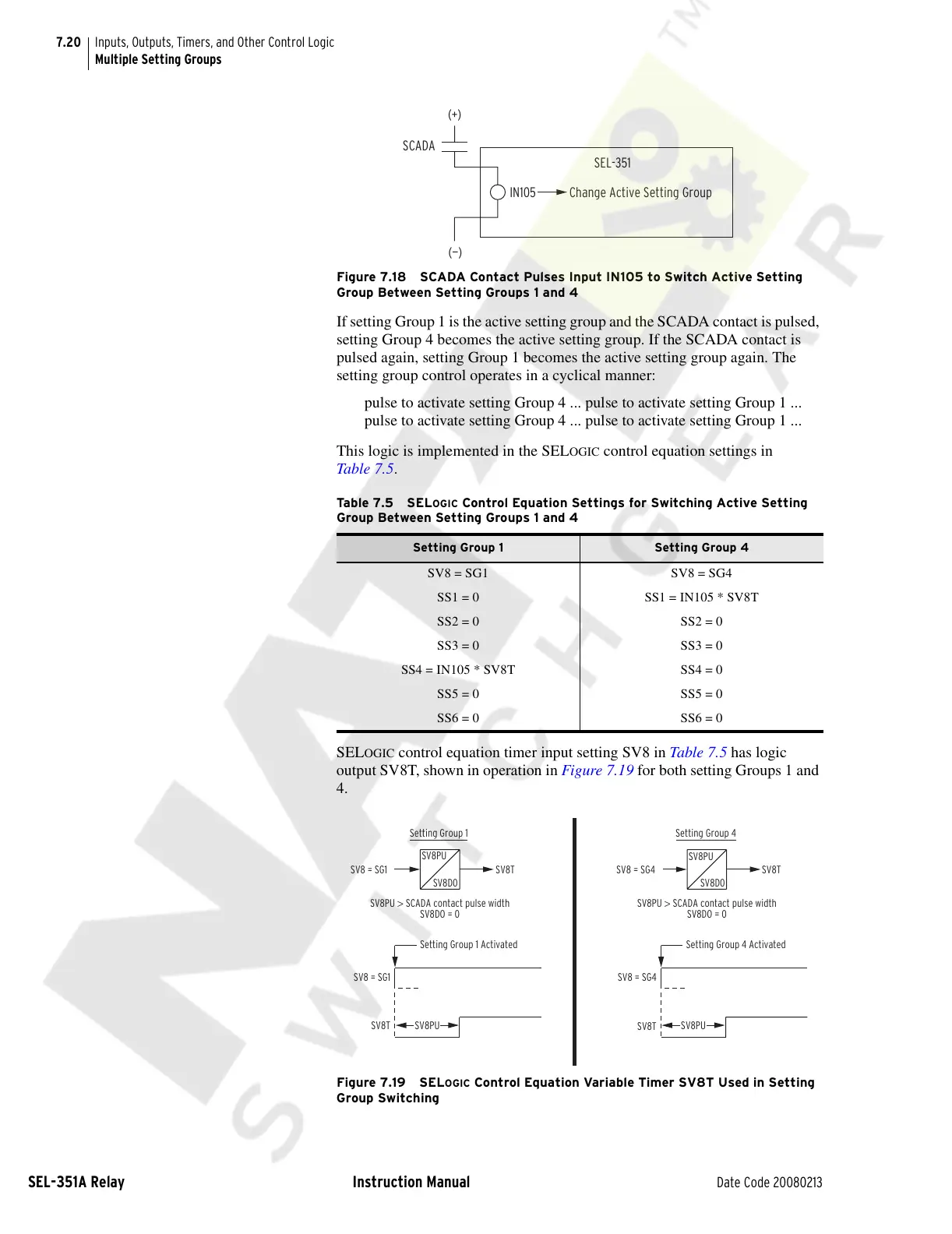
Figure 7.18 SCADA Contact Pulses Input IN105 to Switch Active Setting
Group Between Setting Groups 1 and 4
If setting Group 1 is the active setting group and the SCADA contact is pulsed,
setting Group 4 becomes the active setting group. If the SCADA contact is
pulsed again, setting Group 1 becomes the active setting group again. The
setting group control operates in a cyclical manner:
pulse to activate setting Group 4 ... pulse to activate setting Group 1 ...
pulse to activate setting Group 4 ... pulse to activate setting Group 1 ...
This logic is implemented in the SEL
OGIC control equation settings in
Table 7.5.
SEL
OGIC control equation timer input setting SV8 in Table 7.5 has logic
output SV8T, shown in operation in Figure 7.19 for both setting Groups 1 and
4.
Figure 7.19 SELOGIC Control Equation Variable Timer SV8T Used in Setting
Group Switching
Ta b le 7 . 5 S EL
OGIC Control Equation Settings for Switching Active Setting
Group Between Setting Groups 1 and 4
Setting Group 1 Setting Group 4
SV8 = SG1 SV8 = SG4
SS1 = 0 SS1 = IN105 * SV8T
SS2 = 0 SS2 = 0
SS3 = 0 SS3 = 0
SS4 = IN105 * SV8T SS4 = 0
SS5 = 0 SS5 = 0
SS6 = 0 SS6 = 0
(+)
SCADA
(—)
Change Active Setting Group
SEL-351
IN105
SV8 = SG1
SV8T
Setting Group 1 Activated
SV8PU
SV8 = SG1 SV8T
SV8PU > SCADA contact pulse width
SV8DO = 0
Setting Group 1
SV8 = SG4
SV8 = SG4
Setting Group 4
SV8PU > SCADA contact pulse width
SV8DO = 0
Setting Group 4 Activated
SV8T
SV8PU
SV8T
SV8PU
SV8D0
SV8PU
SV8D0
Courtesy of NationalSwitchgear.com