12.30
SEL-351A Relay Instruction Manual Date Code 20080213
Standard Event Reports and SER
Example Sequential Events Recorder (SER) Report
Example Sequential Events Recorder (SER) Report
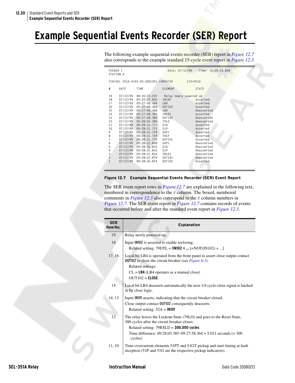
The following example sequential events recorder (SER) report in Figure 12.7
also corresponds to the example standard 15-cycle event report in Figure 12.3.
FEEDER 1 Date: 07/12/99 Time: 10:20:16.896
STATION A
FID=SEL 351A-X103-VO-Z001001-19990730 CID=2516
# DATE TIME ELEMENT STATE
19 07/12/99 08:30:33.222 Relay newly powered up
18 07/12/99 09:20:22.830 IN102 Asserted
17 07/12/99 09:27:58.364 LB4 Asserted
16 07/12/99 09:27:58.364 OUT102 Asserted
15 07/12/99 09:27:58.368 LB4 Deasserted
14 07/12/99 09:27:58.385 IN101 Asserted
13 07/12/99 09:27:58.385 OUT102 Deasserted
12 07/12/99 09:28:03.385 79LO Deasserted
11 07/12/99 09:28:31.717 51G Asserted
10 07/12/99 09:28:31.721 51P Asserted
9 07/12/99 09:28:31.729 50P1 Asserted
8 07/12/99 09:28:31.729 79CY Asserted
7 07/12/99 09:28:31.729 OUT101 Asserted
6 07/12/99 09:28:31.808 50P1 Deasserted
5 07/12/99 09:28:31.816 51G Deasserted
4 07/12/99 09:28:31.816 51P Deasserted
3 07/12/99 09:28:31.816 IN101 Deasserted
2 07/12/99 09:28:31.879 OUT101 Deasserted
1 07/12/99 09:28:36.874 OUT102 Asserted
Figure 12.7 Example Sequential Events Recorder (SER) Event Report
The SER event report rows in Figure 12.7 are explained in the following text,
numbered in correspondence to the
# column. The boxed, numbered
comments in Figure 12.3 also correspond to the
# column numbers in
Figure 12.7. The SER event report in Figure 12.7 contains records of events
that occurred before and after the standard event report in Figure 12.3.
SER
Row No.
Explanation
19 Relay newly powered up.
18 Input IN102 is asserted to enable reclosing.
Related setting: 79DTL = !IN102 + ... [=NOT(IN102) + ...]
17, 16 Local bit LB4 is operated from the front panel to assert close output contact
OUT102 to close the circuit breaker (see Figure 6.1).
Related settings:
CL = LB4 (LB4 operates as a manual close)
OUT102 = CLOSE
15 Local bit LB4 deasserts automatically the next 1/4 cycle-close signal is latched
in by close logic.
14, 13 Input IN101 asserts, indicating that the circuit breaker closed.
Close output contact OUT102 consequently deasserts.
Related setting: 52A = IN101
12 The relay leaves the Lockout State (79LO) and goes to the Reset State,
300 cycles after the circuit breaker closes.
Related setting: 79RSLD = 300.000 cycles
Time difference: 09:28:03.385–09:27:58.364 = 5.021 seconds (= 300
cycles)
11, 10 Time-overcurrent elements 51PT and 51GT pickup and start timing at fault
inception (51P and 51G are the respective pickup indicators).
Courtesy of NationalSwitchgear.com