7.16
SEL-351A Relay Instruction Manual Date Code 20080213
Inputs, Outputs, Timers, and Other Control Logic
Latch Control Switches
latch bit state changes. Exceeding the limit can result in an EEPROM self-test
failure. An average of 70 cumulative latch bit state changes per day can be
made for a 25-year relay service life.
This requires that SEL
OGIC control equation settings SETn and RSTn for any
given latch bit LTn (n = 1–16; see Figure 7.11) be set with care. Settings
SETn and RSTn cannot result in continuous cyclical operation of latch bit
LTn. Use timers to qualify conditions set in settings SETn and RSTn. If any
optoisolated inputs IN101–IN106 are used in settings SETn and RSTn, the inputs
have their own debounce timer that can help in providing the necessary time
qualification (see Figure 7.1).
In the preceding reclosing relay enable/disable example application
(Figure 7.13 and Figure 7.14), the SCADA contact cannot be asserting/
deasserting continuously, thus causing latch bit LT1 to change state
continuously. Note that the rising-edge operators in the SET1 and RST1
settings keep latch bit LT1 from cyclically operating for any single assertion
of the SCADA contact.
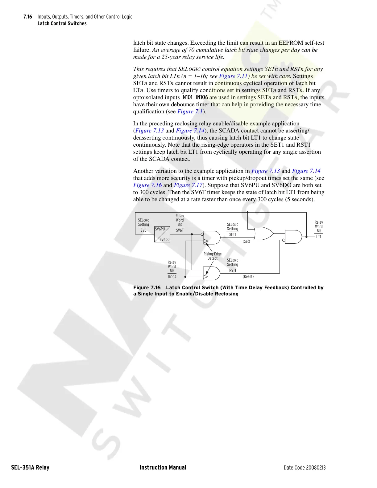
Another variation to the example application in Figure 7.13 and Figure 7.14
that adds more security is a timer with pickup/dropout times set the same (see
Figure 7.16 and Figure 7.17). Suppose that SV6PU and SV6DO are both set
to 300 cycles. Then the SV6T timer keeps the state of latch bit LT1 from being
able to be changed at a rate faster than once every 300 cycles (5 seconds).
Figure 7.16 Latch Control Switch (With Time Delay Feedback) Controlled by
a Single Input to Enable/Disable Reclosing
LT1
IN104
(Set)
(Reset)
Rising-Edge
Detect
SET1
RST1
SELOGIC
Setting
SELOGIC
Setting
SELOGIC
Setting
Relay
Word
Bit
Relay
Word
Bit
Relay
Word
Bit
SV6PU
SV6D0
SV6TSV6
Courtesy of NationalSwitchgear.com