2.24
SEL-351A Relay Instruction Manual Date Code 20080213
Installation
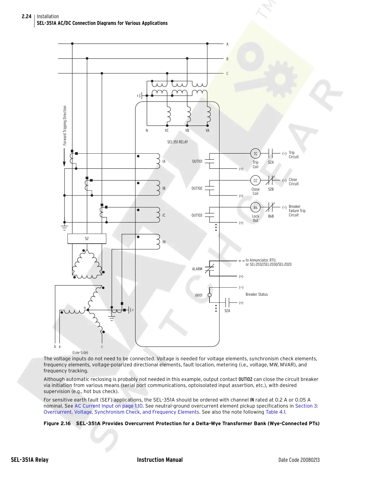
SEL-351A AC/DC Connection Diagrams for Various Applications
The voltage inputs do not need to be connected. Voltage is needed for voltage elements, synchronism check elements,
frequency elements, voltage-polarized directional elements, fault location, metering (i.e., voltage, MW, MVAR), and
frequency tracking.
Although automatic reclosing is probably not needed in this example, output contact OUT102 can close the circuit breaker
via initiation from various means (serial port communications, optoisolated input assertion, etc.), with desired
supervision (e.g., hot bus check).
For sensitive earth fault (SEF) applications, the SEL-351A should be ordered with channel IN rated at 0.2 A or 0.05 A
nominal. See AC Current Input on page 1.10. See neutral-ground overcurrent element pickup specifications in Section 3:
Overcurrent, Voltage, Synchronism Check, and Frequency Elements. See also the note following Table 4.1.
Figure 2.16 SEL-351A Provides Overcurrent Protection for a Delta-Wye Transformer Bank (Wye-Connected PTs)
TC
Trip
Coil
52A
(+)
(—)
Trip
Circuit
IA
C
B
A
NVCVB
SEL-351 RELAY
VA
OUT101
Forward Tripping Direction
CC
Close
Coil
52B
(+)
(—)
Close
Circuit
IB
OUT102
86
Lock
Out
86B
(+)
(—)
Breaker
Failure Trip
Circuit
IC
OUT103
IN
52
(+)
52A
to Annunciator, RTU,
or SEL-2032/SEL-2030/SEL-2020
ALARM
(+)
(—)
Breaker Status
IN101
n
ba c
(Low-Side)
Courtesy of NationalSwitchgear.com