2.16
SEL-351A Relay Instruction Manual Date Code 20080213
Installation
Making Rear-Panel Connections
Polarity Check for VSCONN = 3V0
Refer to Figure 2.8 (wye-connected PTs) or Figure 2.10 (open-delta
connected PTs). With setting VSCONN = 3V0, voltage input VS-NS expects
3V
0
voltage (V
S
= 3V
0
= V
A
+ V
B
+ V
C
) with the polarity shown. However, in
a nonfault, balanced system condition, voltage V
S
= 3V
0
≈ 0. The result is that
a polarity problem with voltage input VS-NS, such as when secondary wires are
on the wrong terminals, will not necessarily be apparent until a ground fault
occurs or testing is performed.
Wye-Connected PT Example
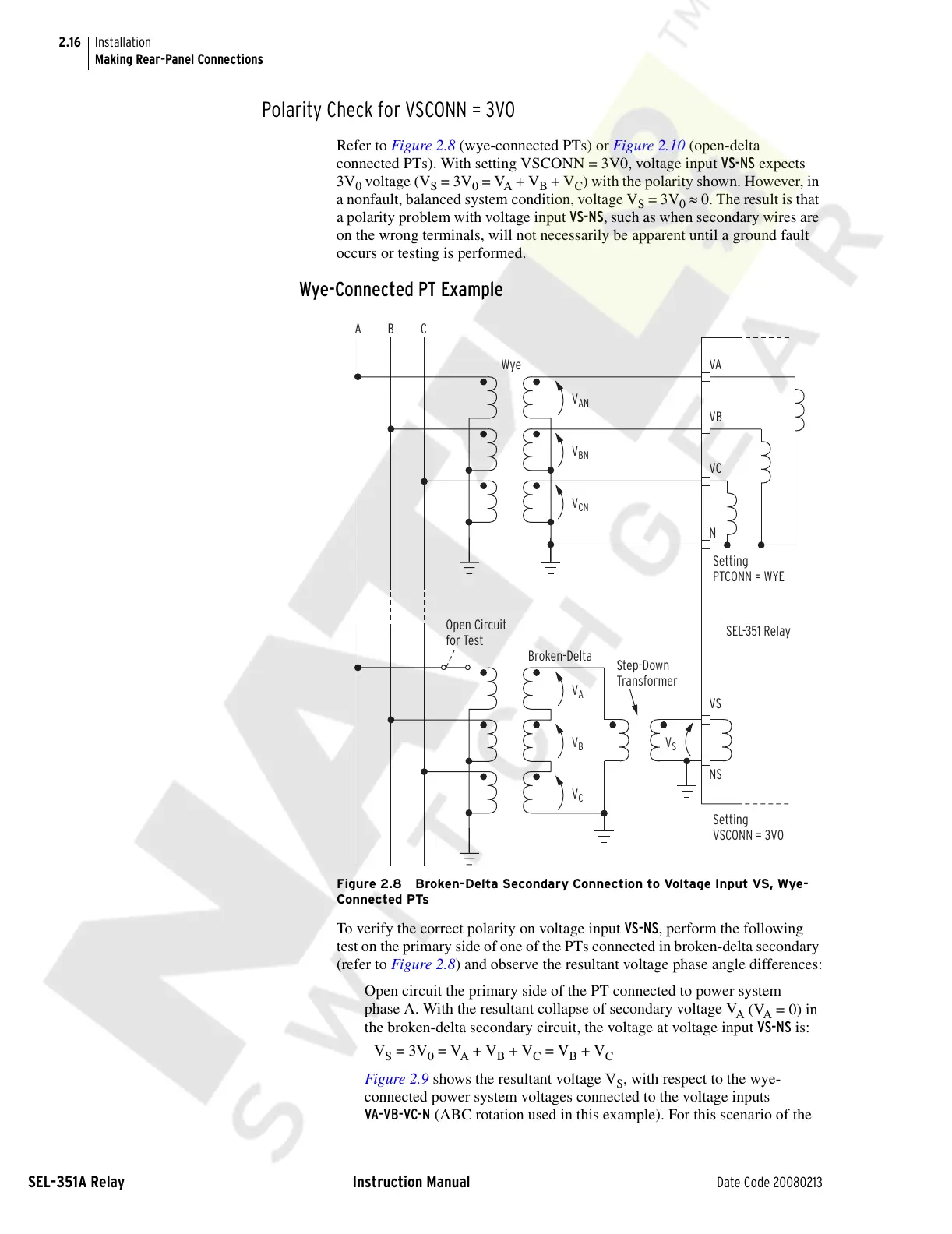
Figure 2.8 Broken-Delta Secondary Connection to Voltage Input VS, Wye-
Connected PTs
To verify the correct polarity on voltage input VS-NS, perform the following
test on the primary side of one of the PTs connected in broken-delta secondary
(refer to Figure 2.8) and observe the resultant voltage phase angle differences:
Open circuit the primary side of the PT connected to power system
phase A. With the resultant collapse of secondary voltage V
A
(V
A
= 0) in
the broken-delta secondary circuit, the voltage at voltage input VS-NS is:
V
S
= 3V
0
= V
A
+ V
B
+ V
C
= V
B
+ V
C
Figure 2.9 shows the resultant voltage V
S
, with respect to the wye-
connected power system voltages connected to the voltage inputs
VA-VB-VC-N (ABC rotation used in this example). For this scenario of the
VS
NS
Setting
VSCONN = 3V0
Open Circuit
for Test
VB
N
Setting
PTCONN = WYE
AB
C
VA
V
AN
V
BN
V
CN
VC
Step-Down
Transformer
SEL-351 Relay
Broken-Delta
Wye
V
A
V
B
V
S
V
C
Courtesy of NationalSwitchgear.com