4.22
SEL-351A Relay Instruction Manual Date Code 20080213
Loss-of-Potential, Load Encroachment, and Directional Element Logic
Directional Control for Neutral-Ground and Residual-Ground Overcurrent Elements (Not in SEL-351A-1)
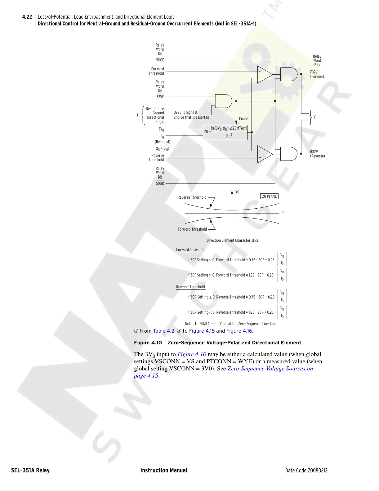
q From Ta b le 4 .2; w to Figure 4.15 and Figure 4.16.
Figure 4.10 Zero-Sequence Voltage-Polarized Directional Element
The 3V
0
input to Figure 4.10 may be either a calculated value (when global
settings VSCONN = VS and PTCONN = WYE) or a measured value (when
global setting VSCONN = 3V0). See Zero-Sequence Voltage Sources on
page 4.15.
I
0
V
0
If Z0F Setting > 0, Forward Threshold = 1.25 • Z0F — 0.25 •
I
0
V
0
If Z0F Setting ≤ 0, Forward Threshold = 0.75 • Z0F — 0.25 •
Forward Threshold:
I
0
V
0
If Z0R Setting < 0, Reverse Threshold = 1.25 • Z0R + 0.25 •
I
0
V
0
If Z0R Setting ≥ 0, Reverse Threshold = 0.75 • Z0R + 0.25 •
Reverse Threshold:
Note: 1∠Z0MTA = One Ohm at the Zero-Sequence Line Angle
Direction Element Characteristics
R0
X0
Forward Threshold
Reverse Threshold
Z0 PLANE
32VE is highest
w
R32V
(Reverse)
F32V
(Forward)
Best Choice
Ground
Directional
Logic
50GF
Enable
Forward
Threshold
32VE
Reverse
Threshold
50GR
q
Re[3V
0
•(I
G
•1
∠
Z0MTA)*]
|I
G
|
2
Z0 =
I
G
3V
0
Relay
Word
Bits
Relay
Word
Bit
Relay
Word
Bit
Relay
Word
Bit
choice that is asserted
(I
G
= 3I
0
)
(Residual)
Courtesy of NationalSwitchgear.com