7.11
Date Code 20080213 Instruction Manual SEL-351A Relay
Inputs, Outputs, Timers, and Other Control Logic
Latch Control Switches
Latch Control Switches
The latch control switch feature of this relay replaces latching relays.
Traditional latching relays maintain their output contact state when set. The
SEL-351A latch bit retains memory even when control power is lost. If the
latch bit is set to a programmable output contact and control power is lost, the
state of the latch bit is stored in nonvolatile memory but the output contact will
go to its de-energized state. When the control power is applied back to the
relay, the programmed output contact will go back to the state of the latch bit
after relay initialization.
The state of a traditional latching relay output contact is changed by pulsing
the latching relay inputs (see Figure 7.10). Pulse the set input to close (“set”)
the latching relay output contact. Pulse (momentarily operate) the reset input
to open (“reset”) the latching relay output contact. Often the external contacts
wired to the latching relay inputs are from remote control equipment (e.g.,
SCADA, RTU).
Figure 7.10 Traditional Latching Relay
The sixteen (16) latch control switches in the SEL-351A provide latching
relay type functions.
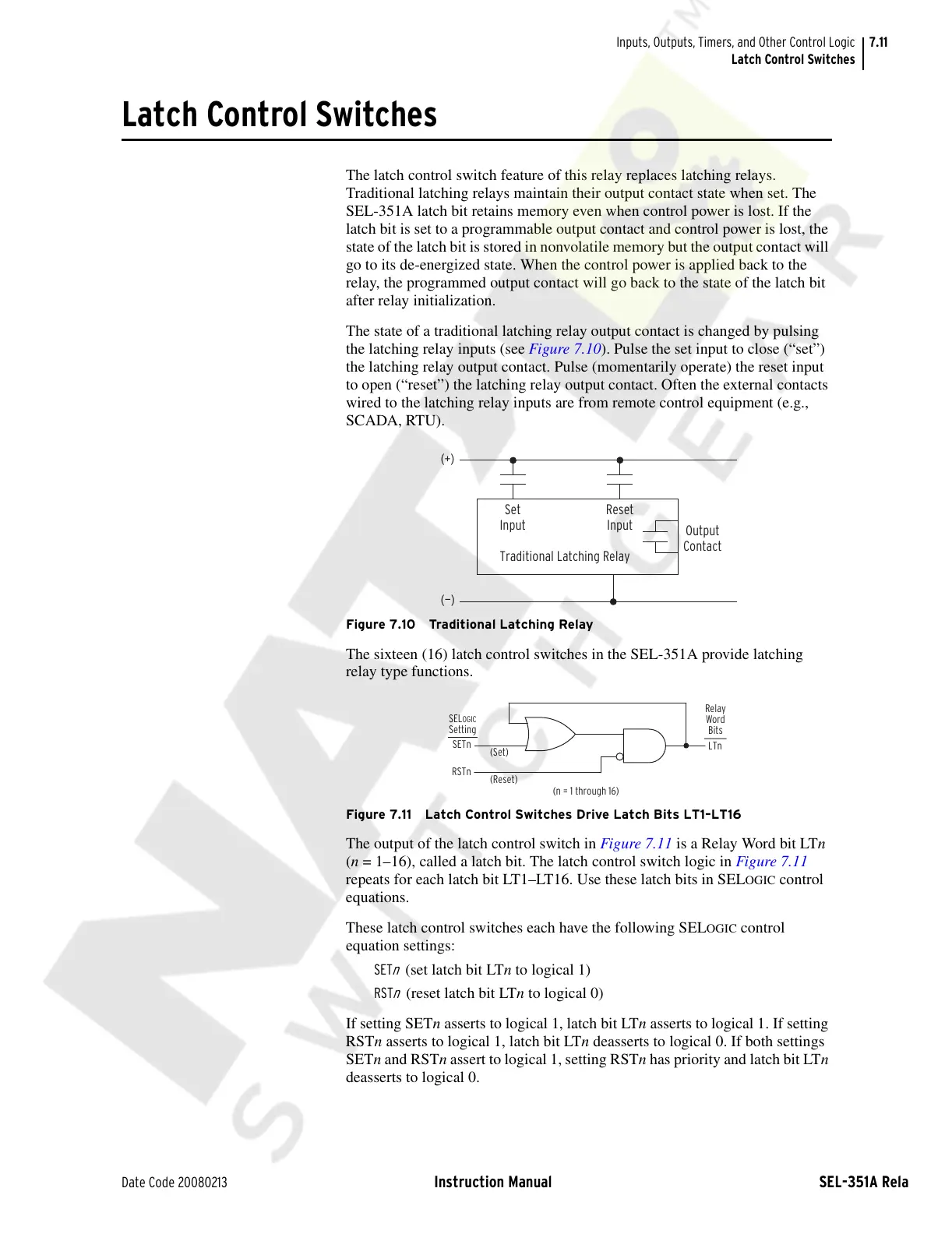
Figure 7.11 Latch Control Switches Drive Latch Bits LT1–LT16
The output of the latch control switch in Figure 7.11 is a Relay Word bit LTn
(n = 1–16), called a latch bit. The latch control switch logic in Figure 7.11
repeats for each latch bit LT1–LT16. Use these latch bits in SEL
OGIC control
equations.
These latch control switches each have the following SEL
OGIC control
equation settings:
SET
n
(set latch bit LTn to logical 1)
RST
n
(reset latch bit LTn to logical 0)
If setting SETn asserts to logical 1, latch bit LTn asserts to logical 1. If setting
RSTn asserts to logical 1, latch bit LTn deasserts to logical 0. If both settings
SETn and RSTn assert to logical 1, setting RSTn has priority and latch bit LTn
deasserts to logical 0.
Output
Contact
Traditional Latching Relay
Reset
Input
Set
Input
(—)
(+)
LTn
SETn
RSTn
(Set)
(Reset)
(n = 1 through 16)
Relay
Word
Bits
SELOGIC
Setting
Courtesy of NationalSwitchgear.com