1.8
SEL-351A Relay Instruction Manual Date Code 20080213
Introduction and Specifications
Hardware Connection Features
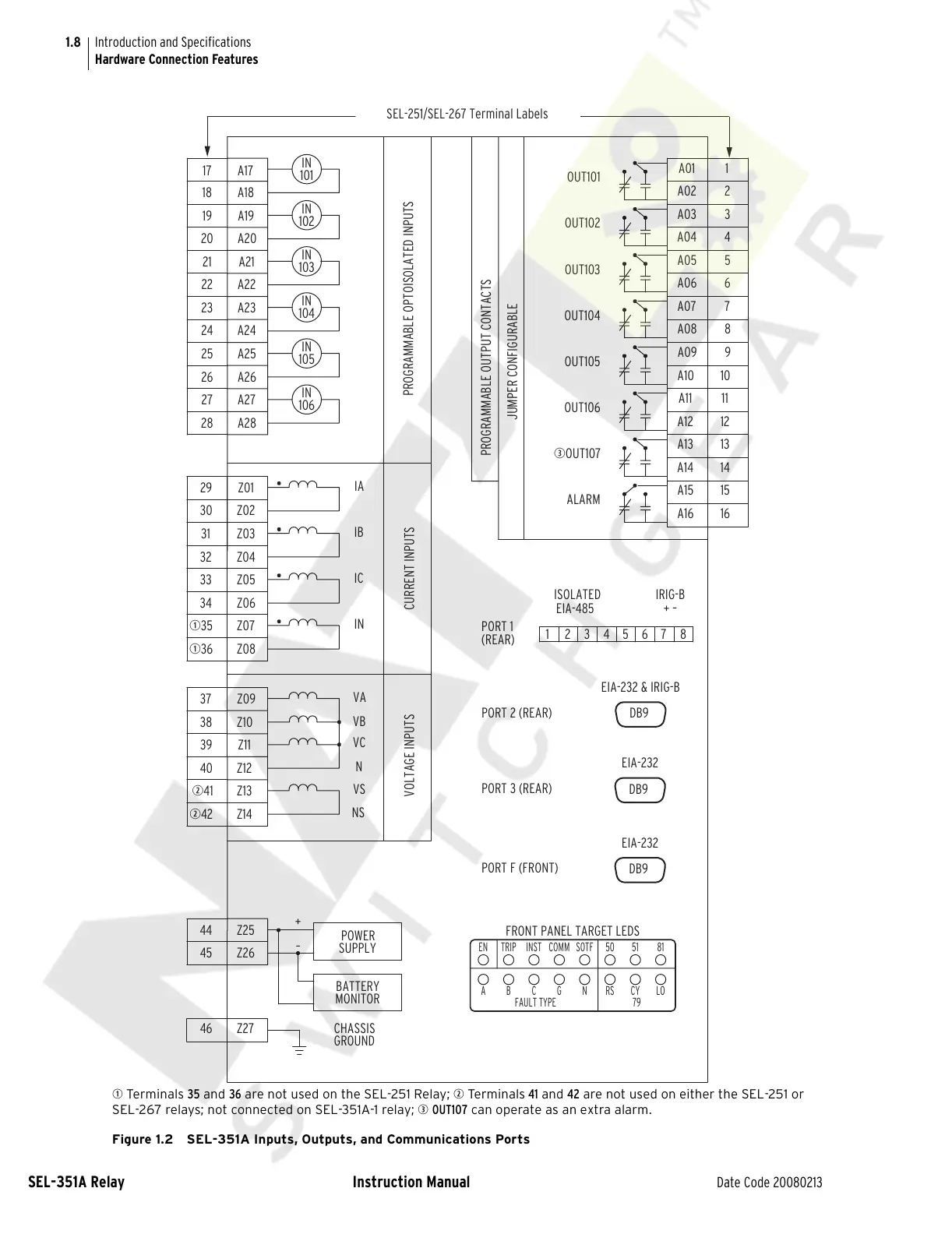
q Terminals 35 and 36 are not used on the SEL-251 Relay; w Te r minal s 41 and 42 are not used on either the SEL-251 or
SEL-267 relays; not connected on SEL-351A-1 relay; e OUT107 can operate as an extra alarm.
Figure 1.2 SEL-351A Inputs, Outputs, and Communications Ports
PORT F (FRONT)
PORT 3 (REAR)
DB9
EIA-232
+ –
IRIG-B
EIA-485
876
(REAR)
JUMPER CONFIGURABLE
IN
105
106
IN
IN
103
IN
104
102
IN
101
IN
A28
A27
A26
A25
A24
A23
A22
A21
A20
A19
A18
A17
Z06
Z08
Z07
Z01
Z05
Z04
Z03
Z02
Z26
Z25
Z14
Z13
Z12
Z11
Z10
Z09
IA
IB
IC
IN
VA
VB
VC
N
VS
NS
PROGRAMMABLE OPTOISOLATED INPUTS
CURRENT INPUTSVOLTAGE INPUTS
Z27
POWER
SUPPLY
BATTERY
MONITOR
–
+
CHASSIS
GROUND
A16
A13
A14
A15
A11
A12
A05
A08
A10
A09
A06
A07
A03
A04
A02
A01
OUT101
OUT102
OUT103
OUT104
OUT105
OUT106
eOUT107
ALARM
PROGRAMMABLE OUTPUT CONTACTS
12345
ISOLATED
DB9
DB9
PORT 1
PORT 2 (REAR)
EIA-232 & IRIG-B
EIA-232
CYB
TRIPEN
A
COMMINST
C G
5150SOTF
RS
79
N
81
LO
FRONT PANEL TARGET LEDS
FAULT TYPE
15
14
16
7
9
10
8
12
11
13
1
2
4
3
6
5
26
28
27
25
24
23
22
19
21
20
18
17
q35
q36
30
31
32
33
29
34
w41
w42
37
38
39
40
44
45
46
SEL-251/SEL-267 Terminal Labels
Courtesy of NationalSwitchgear.com