3.39
Date Code 20080213 Instruction Manual SEL-351A Relay
Overcurrent, Voltage, Synchronism Check, and Frequency Elements
Synchronism Check Elements (Not in SEL-351A-1)
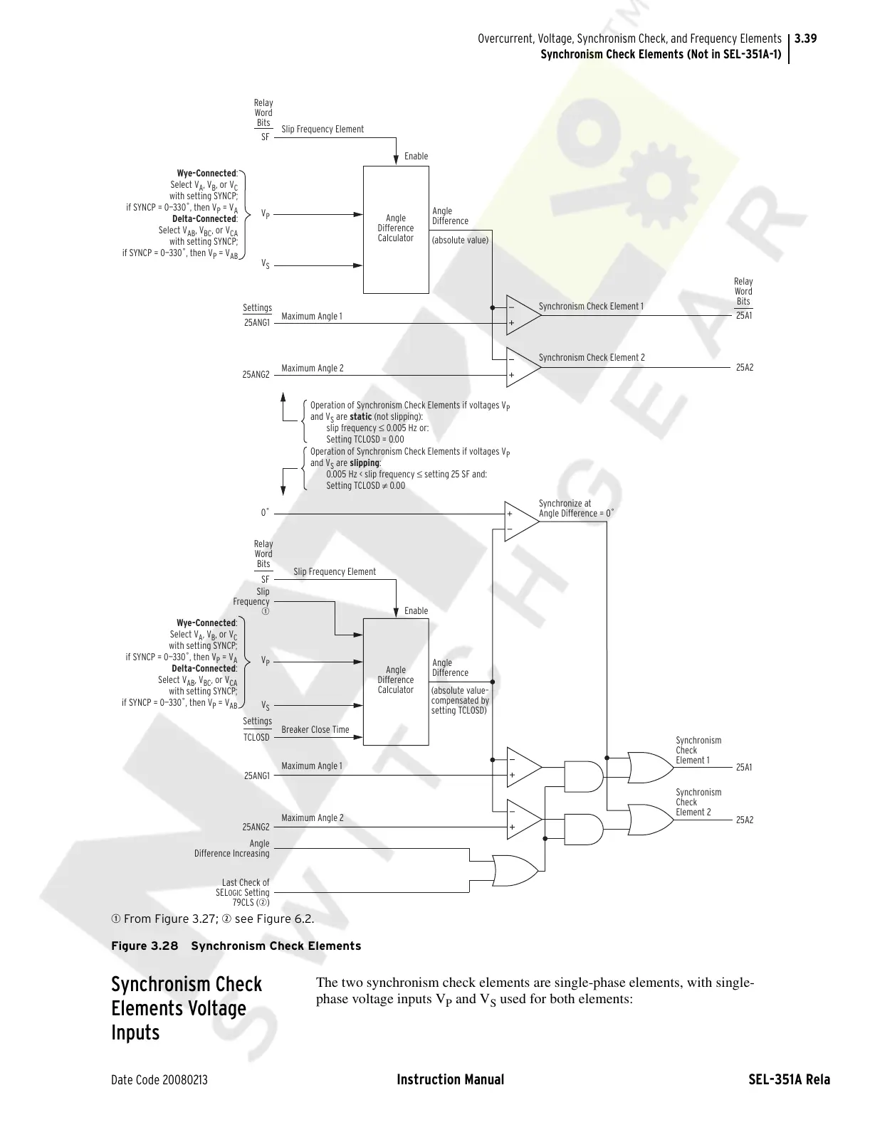
q From Figure 3.27; w see Figure 6.2.
Figure 3.28 Synchronism Check Elements
Synchronism Check
Elements Voltage
Inputs
The two synchronism check elements are single-phase elements, with single-
phase voltage inputs V
P
and V
S
used for both elements:
Wye-Connected:
Select V
A
, V
B
, or V
C
with setting SYNCP;
if SYNCP = 0—330˚, then V
P
= V
A
Delta-Connected:
Select V
AB
, V
BC
, or V
CA
with setting SYNCP;
if SYNCP = 0—330˚, then V
P
= V
AB
Wye-Connected:
Select V
A
, V
B
, or V
C
with setting SYNCP;
if SYNCP = 0—330˚, then V
P
= V
A
Delta-Connected:
Select V
AB
, V
BC
, or V
CA
with setting SYNCP;
if SYNCP = 0—330˚, then V
P
= V
AB
Angle
Difference
Calculator
Angle
Difference
Calculator
Slip Frequency Element
Maximum Angle 1
Maximum Angle 2
Maximum Angle 1
Breaker Close Time
Maximum Angle 2
Slip Frequency Element
SF
V
P
V
P
V
S
V
S
Relay
Word
Bits
SF
Slip
Frequency
q
0˚
Relay
Word
Bits
25A1
25A2
25A1
25A2
Relay
Word
Bits
Angle
Difference
Angle
Difference
Enable
Enable
(absolute value)
(absolute value–
compensated by
setting TCLOSD)
Synchronism Check Element 1
Synchronism Check Element 2
Synchronize at
Angle Difference = 0˚
Operation of Synchronism Check Elements if voltages V
P
and V
S
are static (not slipping):
slip frequency ≤ 0.005 Hz or:
Setting TCLOSD = 0.00
Operation of Synchronism Check Elements if voltages V
P
and V
S
are slipping:
0.005 Hz < slip frequency ≤ setting 25 SF and:
Setting TCLOSD ≠ 0.00
25ANG1
25ANG2
Settings
TCLOSD
25ANG1
25ANG2
Angle
Difference Increasing
Last Check of
SEL
OGIC Setting
79CLS (w)
Settings
Synchronism
Check
Element 1
Synchronism
Check
Element 2
Courtesy of NationalSwitchgear.com