3.26
SEL-351A Relay Instruction Manual Date Code 20080213
Overcurrent, Voltage, Synchronism Check, and Frequency Elements
Time-Overcurrent Elements
Accuracy
Pickup:
±0.05 A secondary and ±3% of setting
(5 A nominal phase current inputs, IA, IB, IC)
±0.01 A secondary and ±3% of setting
(1 A nominal phase current inputs, IA, IB, IC)
Curve Timing:
±1.50 cycles and ±4% of curve time for currents between (and including)
2 and 30 multiples of pickup
Negative-Sequence
Time-Overcurrent
Element
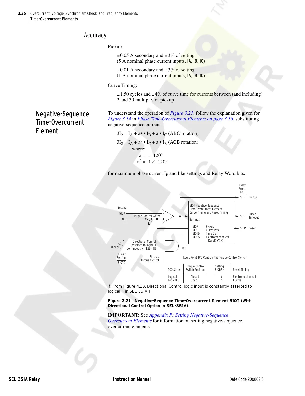
To understand the operation of Figure 3.21, follow the explanation given for
Figure 3.14 in Phase Time-Overcurrent Elements on page 3.16, substituting
negative-sequence current:
3I
2
= I
A
+ a
2
• I
B
+ a • I
C
(ABC rotation)
3I
2
= I
A
+ a
2
• I
C
+ a • I
B
(ACB rotation)
for maximum phase current I
P
and like settings and Relay Word bits.
q From Figure 4.23. Directional Control logic input is constantly asserted to
logical 1 in SEL-351A-1
Figure 3.21 Negative-Sequence Time-Overcurrent Element 51QT (With
Directional Control Option in SEL-351A)
IMPORTANT: See Appendix F: Setting Negative-Sequence
Overcurrent Elements for information on setting negative-sequence
overcurrent elements.
where:
a = ∠ 120°
a
2
=1∠–120°
51QP
31
2
Setting
51QTC
Torque Control Switch
Directional Control
(asserted to logical 1
continuously if E32 = N)
q
(Level 1)
SEL
OGIC
Torque Control
51QT Negative Sequence
Time-Overcurrent Element
Curve Timing and Reset Timing
Settings
51QP Pickup
51QC Curve Type
51QTD Time Dial
51QRS Electromechanical
Reset? (Y/N)
Pickup
Curve
Timeout
Reset
51Q
51QR
51QT
Torque Control
TCQ State Switch Position
Logical 1 Closed
Logical 0 Open
Logic Point TCQ Controls the Torque Control Switch
Setting
51QRS = Reset Timing
Y Electromechanical
N 1 Cycle
TCQ
Relay
Word
Bits
SELOGIC
Setting
Courtesy of NationalSwitchgear.com