4.20
SEL-351A Relay Instruction Manual Date Code 20080213
Loss-of-Potential, Load Encroachment, and Directional Element Logic
Directional Control for Neutral-Ground and Residual-Ground Overcurrent Elements (Not in SEL-351A-1)
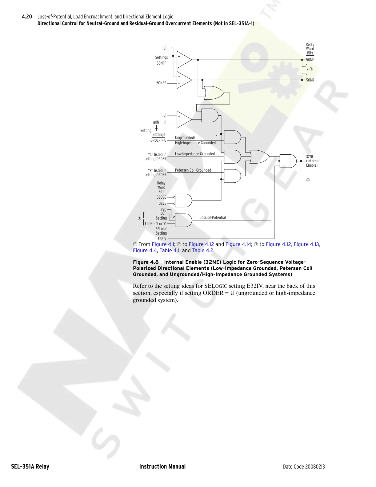
q From Figure 4.1; w to Figure 4.12 and Figure 4.14; e to Figure 4.12, Figure 4.13,
Figure 4.4, Tab le 4 .1, and Ta ble 4.2.
Figure 4.8 Internal Enable (32NE) Logic for Zero-Sequence Voltage-
Polarized Directional Elements (Low-Impedance Grounded, Petersen Coil
Grounded, and Ungrounded/High-Impedance Grounded Systems)
Refer to the setting ideas for SELOGIC setting E32IV, near the back of this
section, especially if setting ORDER = U (ungrounded or high-impedance
grounded system).
3V0
q
Loss-of-Potential
32NE
(Internal
Enable)
High-Impedance Grounded
e
ORDER = U
Ungrounded/
Petersen Coil Grounded
Low-Impedance Grounded
LOP
"P" listed in
setting ORDER
32VE
32QGE
"S" listed in
setting ORDER
w
ELOP = Y or Y1
E32IV
50NF
50NR
50NRP
50NFP
Setting
Relay
Word
Bits
Relay
Word
Bits
Settings
Settings
Setting
SEL
OGIC
Setting
a0N • |I
1
|
|I
N
|
|I
N
|
Courtesy of NationalSwitchgear.com