3.45
Date Code 20080213 Instruction Manual SEL-351A Relay
Overcurrent, Voltage, Synchronism Check, and Frequency Elements
Synchronism Check Elements (Not in SEL-351A-1)
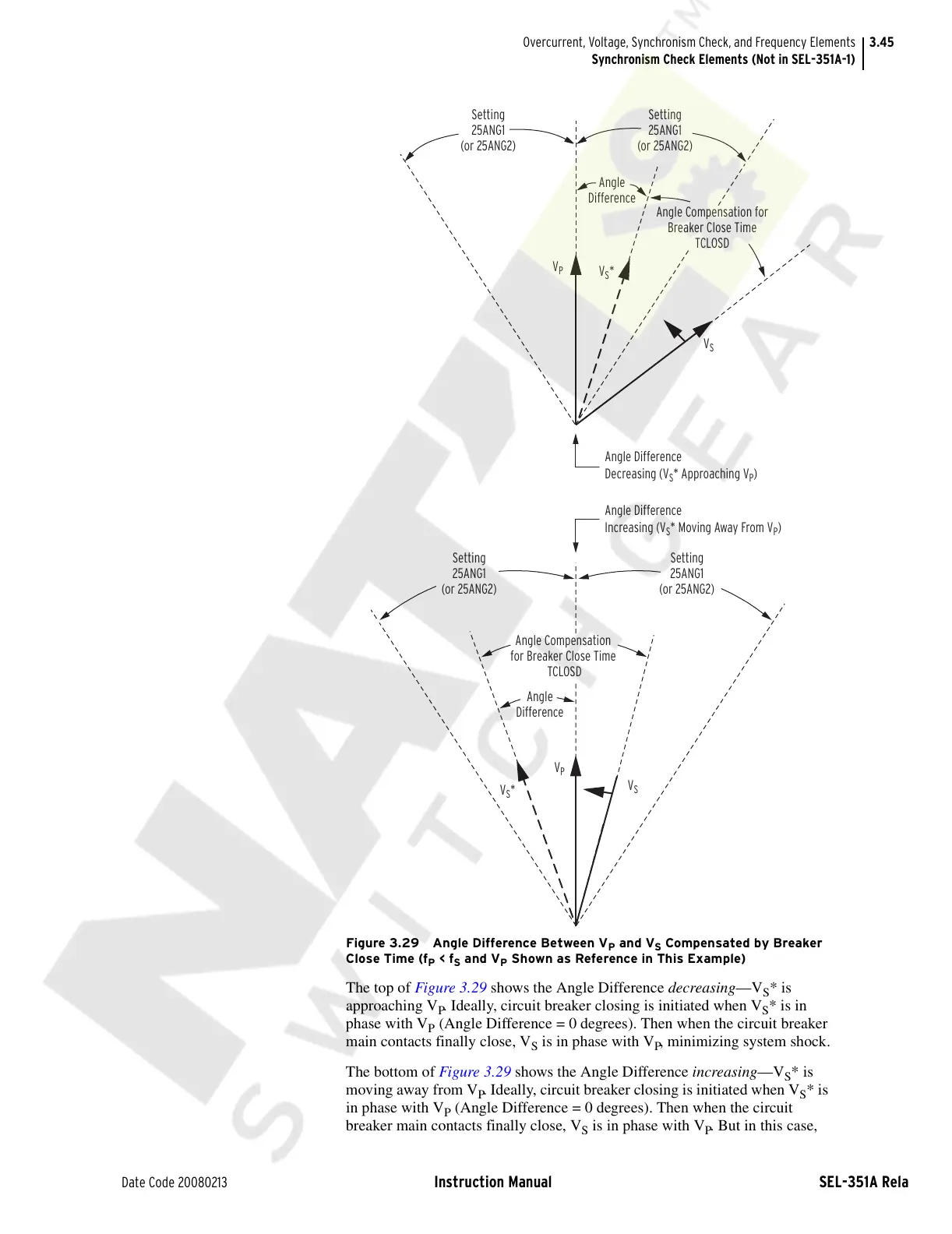
Figure 3.29 Angle Difference Between V
P
and V
S
Compensated by Breaker
Close Time (f
P
< f
S
and V
P
Shown as Reference in This Example)
The top of Figure 3.29 shows the Angle Difference decreasing—V
S
* is
approaching V
P
. Ideally, circuit breaker closing is initiated when V
S
* is in
phase with V
P
(Angle Difference = 0 degrees). Then when the circuit breaker
main contacts finally close, V
S
is in phase with V
P
, minimizing system shock.
The bottom of Figure 3.29 shows the Angle Difference increasing—V
S
* is
moving away from V
P
. Ideally, circuit breaker closing is initiated when V
S
* is
in phase with V
P
(Angle Difference = 0 degrees). Then when the circuit
breaker main contacts finally close, V
S
is in phase with V
P
. But in this case,
Angle Difference
Decreasing (V
S
* Approaching V
P
)
Angle Difference
Increasing (V
S
* Moving Away From V
P
)
Angle
Difference
Angle
Difference
Angle Compensation for
Breaker Close Time
TCLOSD
Angle Compensation
for Breaker Close Time
TCLOSD
Setting
25ANG1
(or 25ANG2)
Setting
25ANG1
(or 25ANG2)
Setting
25ANG1
(or 25ANG2)
V
P
V
S
V
S
*
V
S
*
V
P
V
S
Setting
25ANG1
(or 25ANG2)
Courtesy of NationalSwitchgear.com

 Loading...