3.44
SEL-351A Relay Instruction Manual Date Code 20080213
Overcurrent, Voltage, Synchronism Check, and Frequency Elements
Synchronism Check Elements (Not in SEL-351A-1)
Equation 3.3
Angle Difference Example (Voltages V
p
and V
s
are “Slipping”)
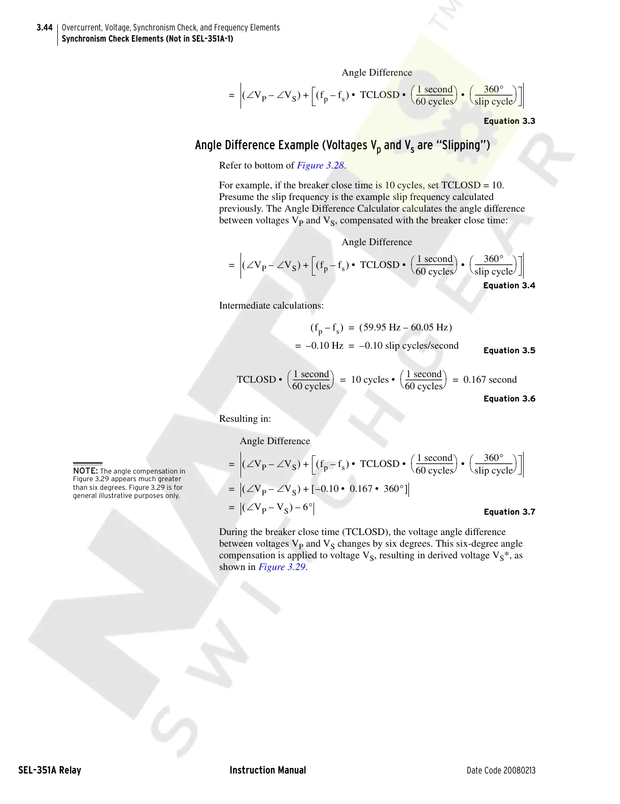
Refer to bottom of Figure 3.28.
For example, if the breaker close time is 10 cycles, set TCLOSD = 10.
Presume the slip frequency is the example slip frequency calculated
previously. The Angle Difference Calculator calculates the angle difference
between voltages V
P
and V
S
, compensated with the breaker close time:
Equation 3.4
Intermediate calculations:
Equation 3.5
Equation 3.6
Resulting in:
Equation 3.7
During the breaker close time (TCLOSD), the voltage angle difference
between voltages V
P
and V
S
changes by six degrees. This six-degree angle
compensation is applied to voltage V
S
, resulting in derived voltage V
S
*, as
shown in Figure 3.29.
Angle Difference
V
P
V∠
S
–∠()f
p
f
s
–()TCLOSD
1 second
60 cycles
----------------------
⎝⎠
⎛⎞
360°
slip cycle
----------------------
⎝⎠
⎛⎞
• • • +=
Angle Difference
V
P
V∠
S
–∠()f
p
f
s
–()TCLOSD
1 second
60 cycles
----------------------
⎝⎠
⎛⎞
360°
slip cycle
----------------------
⎝⎠
⎛⎞
• • • +=
f
p
f
s
–()59.95 Hz 60.05 Hz–()=
0.10 Hz–= 0.10 slip cycles/second–=
TCLOSD
1 second
60 cycles
----------------------
⎝⎠
⎛⎞
• 10 cycles
1 second
60 cycles
----------------------
⎝⎠
⎛⎞
• 0.167 second==
Angle Difference
V
P
V∠
S
–∠()f
p
f
s
–()TCLOSD
1 second
60 cycles
----------------------
⎝⎠
⎛⎞
360°
slip cycle
----------------------
⎝⎠
⎛⎞
• • • +=
V
P
∠ V
S
∠–()0.10 0.167 360°• • –[]+=
V
P
V
S
–∠()6°–=
NOTE: The angle compensation in
Figure 3.29 appears much greater
than six degrees. Figure 3.29 is for
general illustrative purposes only.
Courtesy of NationalSwitchgear.com
 Loading...