7.2
SEL-351A Relay Instruction Manual Date Code 20080213
Inputs, Outputs, Timers, and Other Control Logic
Optoisolated Inputs
Optoisolated Inputs
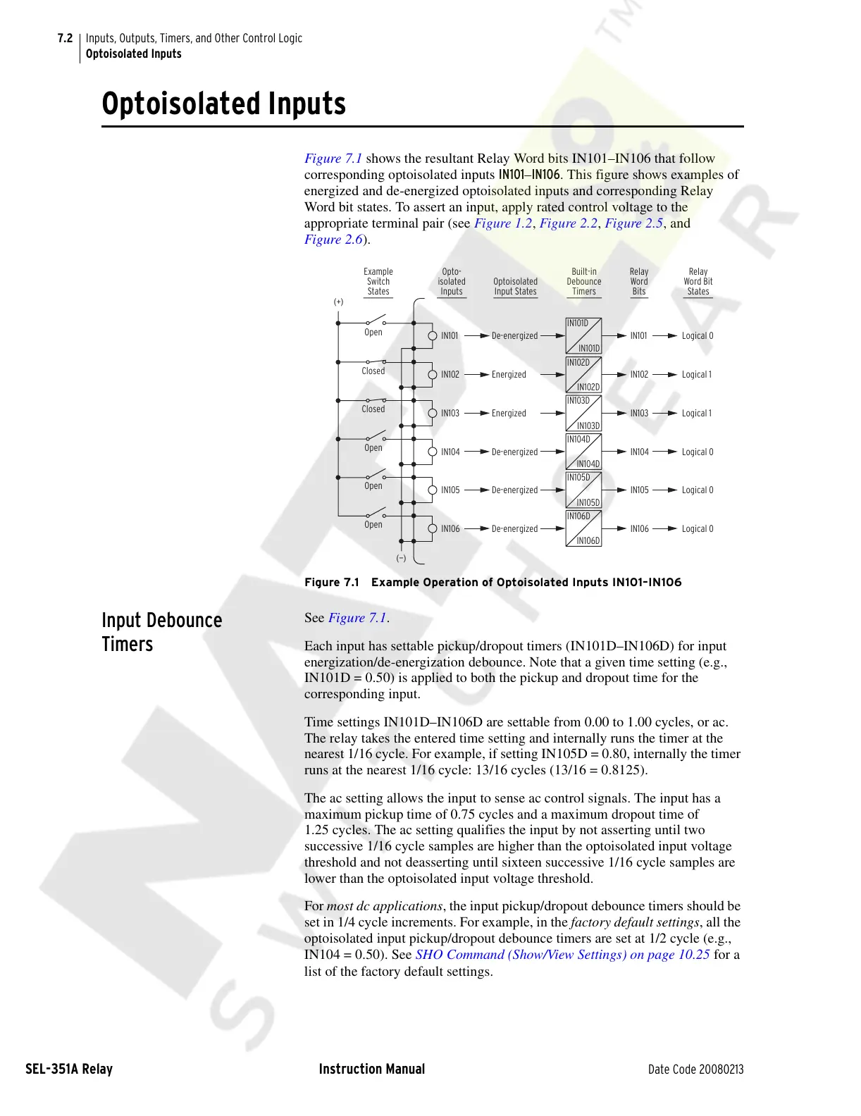
Figure 7.1 shows the resultant Relay Word bits IN101–IN106 that follow
corresponding optoisolated inputs IN101–IN106. This figure shows examples of
energized and de-energized optoisolated inputs and corresponding Relay
Word bit states. To assert an input, apply rated control voltage to the
appropriate terminal pair (see Figure 1.2, Figure 2.2, Figure 2.5, and
Figure 2.6).
Figure 7.1 Example Operation of Optoisolated Inputs IN101–IN106
Input Debounce
Timers
See Figure 7.1.
Each input has settable pickup/dropout timers (IN101D–IN106D) for input
energization/de-energization debounce. Note that a given time setting (e.g.,
IN101D = 0.50) is applied to both the pickup and dropout time for the
corresponding input.
Time settings IN101D–IN106D are settable from 0.00 to 1.00 cycles, or ac.
The relay takes the entered time setting and internally runs the timer at the
nearest 1/16 cycle. For example, if setting IN105D = 0.80, internally the timer
runs at the nearest 1/16 cycle: 13/16 cycles (13/16 = 0.8125).
The ac setting allows the input to sense ac control signals. The input has a
maximum pickup time of 0.75 cycles and a maximum dropout time of
1.25 cycles. The ac setting qualifies the input by not asserting until two
successive 1/16 cycle samples are higher than the optoisolated input voltage
threshold and not deasserting until sixteen successive 1/16 cycle samples are
lower than the optoisolated input voltage threshold.
For most dc applications, the input pickup/dropout debounce timers should be
set in 1/4 cycle increments. For example, in the factory default settings, all the
optoisolated input pickup/dropout debounce timers are set at 1/2 cycle (e.g.,
IN104 = 0.50). See SHO Command (Show/View Settings) on page 10.25 for a
list of the factory default settings.
Open
IN101 IN101 Logical 0De-energized
Opto-
isolated
Inputs
Example
Switch
States
Built-in
Debounce
Timers
Relay
Word
Bits
Relay
Word Bit
States
Optoisolated
Input States
(+)
(—)
IN101D
IN101D
Closed
IN102 IN102 Logical 1
Energized
IN102D
IN102D
Closed
IN103 IN103 Logical 1
Energized
IN103D
IN103D
Open
IN104 IN104 Logical 0
De-energized
IN104D
IN104D
Open
IN105 IN105 Logical 0
De-energized
IN105D
IN105D
Open
IN106 IN106 Logical 0De-energized
IN106D
IN106D
Courtesy of NationalSwitchgear.com