2.36
SEL-351A Relay Instruction Manual Date Code 20080213
Installation
Circuit Board Connections
“Extra Alarm” Output
Contact Control
Jumper
The SEL-351A has dedicated alarm output contacts (labeled ALARM—see
Figure 2.2). Often more than one alarm output contact is needed for such
applications as local or remote annunciation, backup schemes, etc. An extra
alarm output contact can be added for the SEL-351A model without the
addition of any external hardware.
The output contact next to the dedicated ALARM output contact can be
converted to operate as an “extra alarm” output contact by moving a jumper
on the main board (see Table 2.3).
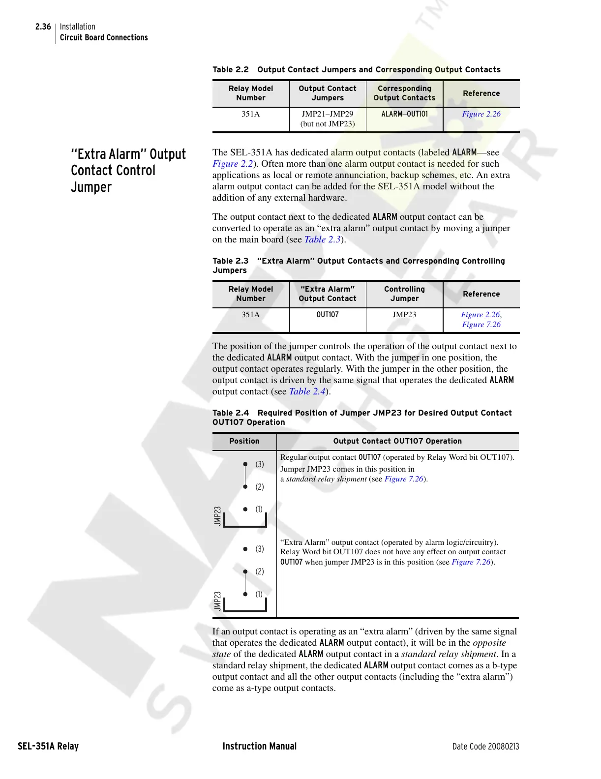
The position of the jumper controls the operation of the output contact next to
the dedicated ALARM output contact. With the jumper in one position, the
output contact operates regularly. With the jumper in the other position, the
output contact is driven by the same signal that operates the dedicated ALARM
output contact (see Table 2.4).
If an output contact is operating as an “extra alarm” (driven by the same signal
that operates the dedicated ALARM output contact), it will be in the opposite
state of the dedicated ALARM output contact in a standard relay shipment. In a
standard relay shipment, the dedicated ALARM output contact comes as a b-type
output contact and all the other output contacts (including the “extra alarm”)
come as a-type output contacts.
Table 2.2 Output Contact Jumpers and Corresponding Output Contacts
Relay Model
Number
Output Contact
Jumpers
Corresponding
Output Contacts
Reference
351A JMP21–JMP29
(but not JMP23)
ALARM–OUT101 Figure 2.26
Table 2.3 “Extra Alarm” Output Contacts and Corresponding Controlling
Jumpers
Relay Model
Number
“Extra Alarm”
Output Contact
Controlling
Jumper
Reference
351A OUT107 JMP23 Figure 2.26,
Figure 7.26
Table 2.4 Required Position of Jumper JMP23 for Desired Output Contact
OUT107 Operation
Position Output Contact OUT107 Operation
Regular output contact OUT107 (operated by Relay Word bit OUT107).
Jumper JMP23 comes in this position in
a standard relay shipment (see Figure 7.26).
“Extra Alarm” output contact (operated by alarm logic/circuitry).
Relay Word bit OUT107 does not have any effect on output contact
OUT107 when jumper JMP23 is in this position (see Figure 7.26).
JMP23
(3)
(2)
(1)
JMP23
(3)
(2)
(1)
Courtesy of NationalSwitchgear.com