4.25
Date Code 20080213 Instruction Manual SEL-351A Relay
Loss-of-Potential, Load Encroachment, and Directional Element Logic
Directional Control for Neutral-Ground and Residual-Ground Overcurrent Elements (Not in SEL-351A-1)
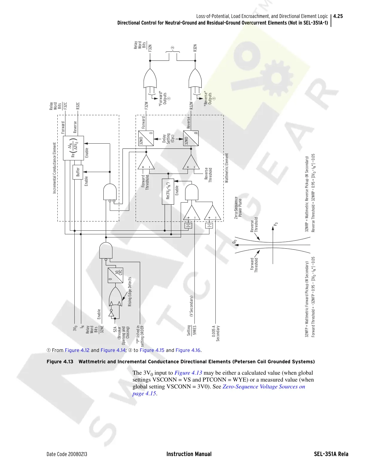
q From Figure 4.12 and Figure 4.14; w to Figure 4.15 and Figure 4.16.
Figure 4.13 Wattmetric and Incremental Conductance Directional Elements (Petersen Coil Grounded Systems)
The 3V
0
input to Figure 4.13 may be either a calculated value (when global
settings VSCONN = VS and PTCONN = WYE) or a measured value (when
global setting VSCONN = 3V0). See Zero-Sequence Voltage Sources on
page 4.15.
P
0
Reverse
Threshold
Forward
Threshold
Q
0
Zero-Sequence
Power Plane
Forward Threshold = —32WFP • 0.95 — |3V
0
• I
N
*| • 0.05
32WFP = Wattmetric Forward Pickup (W Secondary) 32WRP = Wattmetric Reverse Pickup (W Secondary)
Reverse Threshold = 32WRP • 0.95 + |3V
0
• I
N
*| • 0.05
Re(3V
0
•I
N
*)
Enable
0
32WD
0
32WD
Forward
Reverse
R32W
F32W
Delay
Setting
(Cyc)
Reverse
Threshold
Forward
Threshold
Wattmetric Element
Buffer
Enable
Enable
F32C
R32C
Forward
Reverse
Incremental Conductance Element
CYC
30
0
Rising Edge Detects
0.005 A
Secondary
59RES
(V Secondary)
52A
(Breaker
Opening and
Closing)
Enable
32NE
3V
0
I
N
"P" listed in
setting ORDER
( )
Re
ΔI
N
Δ3V
0
w
R32N
F32N
Relay
Word
Bits
Relay
Word
Bits
"Forward"
Outputs
q
"Reverse"
Outputs
q
|•|
|•|
Relay
Word
Bits
Setting
Courtesy of NationalSwitchgear.com