10.2
SEL-351A Relay Instruction Manual Date Code 20080213
Serial Port Communications and Commands
Port Connector and Communications Cables
Port Connector and Communications Cables
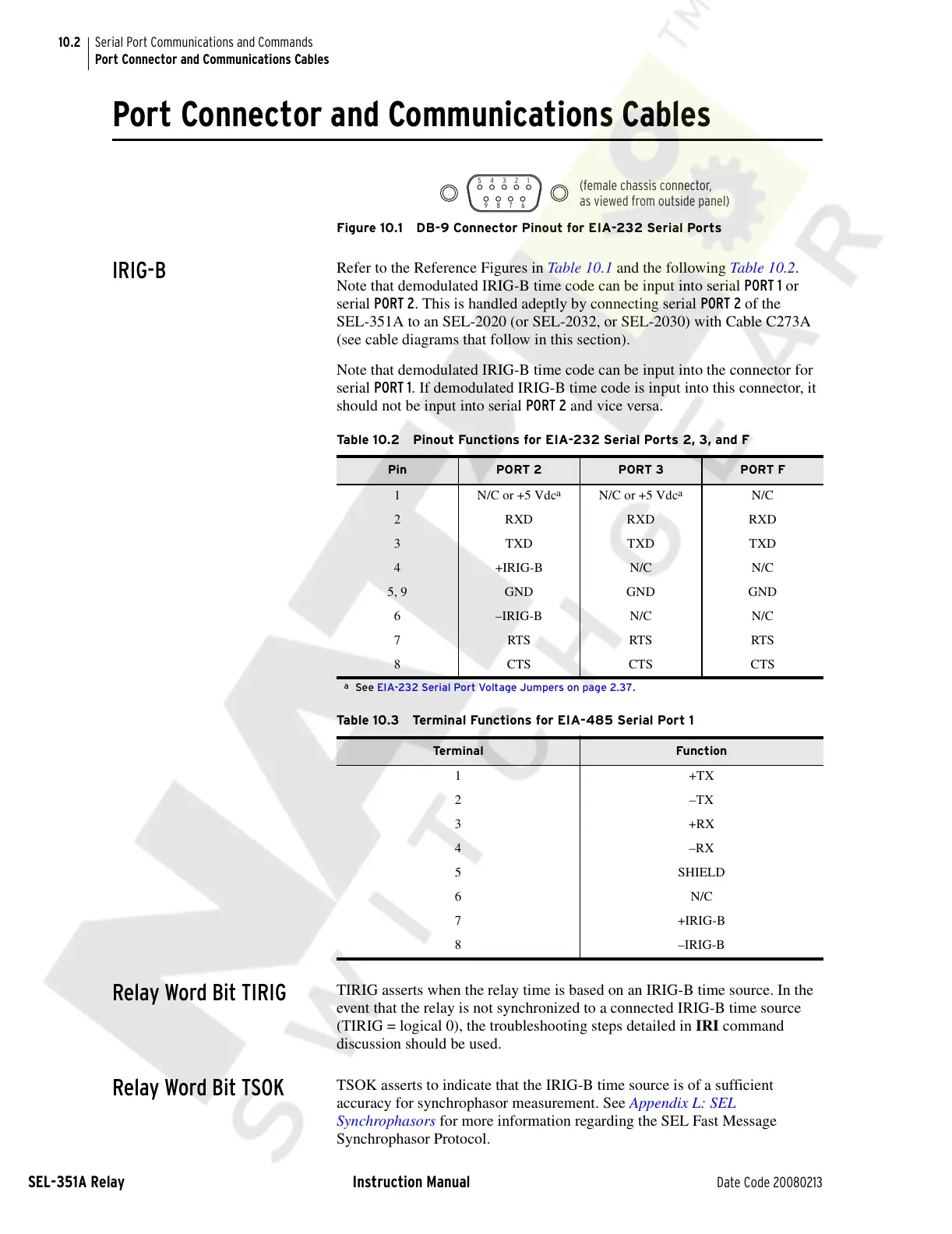
Figure 10.1 DB-9 Connector Pinout for EIA-232 Serial Ports
IRIG-B
Refer to the Reference Figures in Table 10.1 and the following Table 10.2.
Note that demodulated IRIG-B time code can be input into serial PORT 1 or
serial PORT 2. This is handled adeptly by connecting serial PORT 2 of the
SEL-351A to an SEL-2020 (or SEL-2032, or SEL-2030) with Cable C273A
(see cable diagrams that follow in this section).
Note that demodulated IRIG-B time code can be input into the connector for
serial PORT 1. If demodulated IRIG-B time code is input into this connector, it
should not be input into serial PORT 2 and vice versa.
Relay Word Bit TIRIG
TIRIG asserts when the relay time is based on an IRIG-B time source. In the
event that the relay is not synchronized to a connected IRIG-B time source
(TIRIG = logical 0), the troubleshooting steps detailed in IRI command
discussion should be used.
Relay Word Bit TSOK
TSOK asserts to indicate that the IRIG-B time source is of a sufficient
accuracy for synchrophasor measurement. See Appendix L: SEL
Synchrophasors for more information regarding the SEL Fast Message
Synchrophasor Protocol.
5 4 3 2 1
9 8 7 6
(female chassis connector,
as viewed from outside panel)
Table 10.2 Pinout Functions for EIA-232 Serial Ports 2, 3, and F
Pin PORT 2 PORT 3 PORT F
1 N/C or +5 Vdc
a
a
See EIA-232 Serial Port Voltage Jumpers on page 2.37.
N/C or +5 Vdc
a
N/C
2 RXD RXD RXD
3 TXD TXD TXD
4 +IRIG-B N/C N/C
5, 9 GND GND GND
6 –IRIG-B N/C N/C
7 RTS RTS RTS
8 CTS CTS CTS
Table 10.3 Terminal Functions for EIA-485 Serial Port 1
Termin a l Function
1+TX
2–TX
3+RX
4–RX
5SHIELD
6N/C
7 +IRIG-B
8 –IRIG-B
Courtesy of NationalSwitchgear.com