4.19
Date Code 20080213 Instruction Manual SEL-351A Relay
Loss-of-Potential, Load Encroachment, and Directional Element Logic
Directional Control for Neutral-Ground and Residual-Ground Overcurrent Elements (Not in SEL-351A-1)
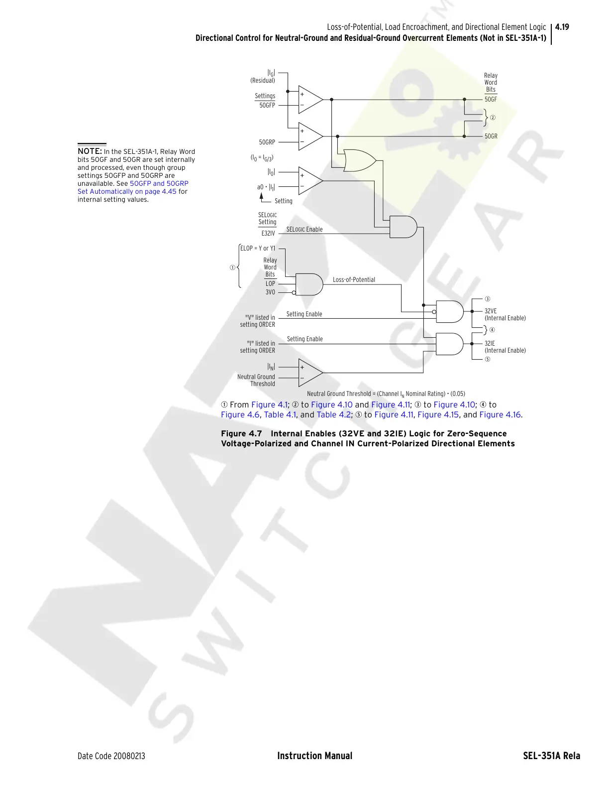
q From Figure 4.1; w to Figure 4.10 and Figure 4.11; e to Figure 4.10; r to
Figure 4.6, Tab le 4 .1, and Tabl e 4 .2; t to Figure 4.11, Figure 4.15, and Figure 4.16.
Figure 4.7 Internal Enables (32VE and 32IE) Logic for Zero-Sequence
Voltage-Polarized and Channel IN Current-Polarized Directional Elements
3V0
q
Loss-of-Potential
ELOP = Y or Y1
LOP
t
"I" listed in
setting ORDER
Setting Enable
Setting Enable
"V" listed in
setting ORDER
r
32IE
(Internal Enable)
e
32VE
(Internal Enable)
w
Neutral Ground Threshold = (Channel I
N
Nominal Rating) • (0.05)
|I
N
|
E32IV
50GF
50GR
Neutral Ground
Threshold
50GRP
50GFP
Setting
|I
G
|
(Residual)
Relay
Word
Bits
SELOGIC Enable
Relay
Word
Bits
(I
0
= I
G/3
)
|I
0
|
a0 • |I
1
|
Settings
SELOGIC
Setting
NOTE: In the SEL-351A-1, Relay Word
bits 50GF and 50GR are set internally
and processed, even though group
settings 50GFP and 50GRP are
unavailable. See 50GFP and 50GRP
Set Automatically on page 4.45 for
internal setting values.
Courtesy of NationalSwitchgear.com