H.16
SEL-351A Relay Instruction Manual Date Code 20080213
Distributed Network Protocol
Data Map
Binary inputs (objects 1 and 2) are supported as defined by the previous table.
Binary inputs 0–499, 1000–1023, and 1025 are scanned approximately once
per second to generate events. When time is reported with these event objects,
it is the time at which the scanner observed the bit change. This may be
significantly delayed from when the original source changed and should not
be used for sequence-of-events determination.
In order to determine an element’s point index, consult Table 9.5. Locate the
element in question in the table and note the Relay Word row number. From
that row number, subtract the row number of the first Relay Word row (usually
2) and multiply that result by 8. This is the index of the right-most element of
the Relay Word row of the element in question. Count over to the original
element and add that to get the point index. Binary Inputs 500–999 are derived
from the Sequential Events Recorder (SER) and carry the time stamp of actual
occurrence. Static reads from these inputs will show the same data as a read
from the corresponding index in the 0–499 group. Only points that are actually
in the SER list (SET R) will generate events in the 500–999 group.
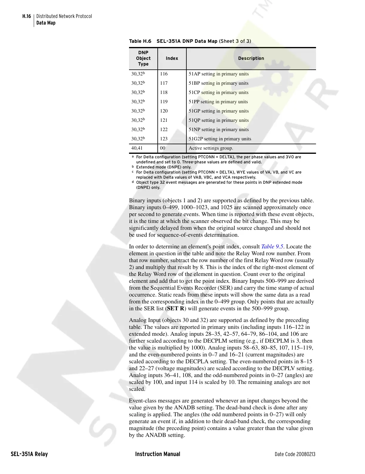
Analog Input (objects 30 and 32) are supported as defined by the preceding
table. The values are reported in primary units (including inputs 116–122 in
extended mode). Analog inputs 28–35, 42–57, 64–79, 86–104, and 106 are
further scaled according to the DECPLM setting (e.g., if DECPLM is 3, then
the value is multiplied by 1000). Analog inputs 58–63, 80–85, 107, 115–119,
and the even-numbered points in 0–7 and 16–21 (current magnitudes) are
scaled according to the DECPLA setting. The even-numbered points in 8–15
and 22–27 (voltage magnitudes) are scaled according to the DECPLV setting.
Analog inputs 36–41, 108, and the odd-numbered points in 0–27 (angles) are
scaled by 100, and input 114 is scaled by 10. The remaining analogs are not
scaled.
Event-class messages are generated whenever an input changes beyond the
value given by the ANADB setting. The dead-band check is done after any
scaling is applied. The angles (the odd numbered points in 0–27) will only
generate an event if, in addition to their dead-band check, the corresponding
magnitude (the preceding point) contains a value greater than the value given
by the ANADB setting.
30,32
b
116 51AP setting in primary units
30,32
b
117 51BP setting in primary units
30,32
b
118 51CP setting in primary units
30,32
b
119 51PP setting in primary units
30,32
b
120 51GP setting in primary units
30,32
b
121 51QP setting in primary units
30,32
b
122 51NP setting in primary units
30,32
b
123 51G2P setting in primary units
40,41 00 Active settings group.
a
For Delta configuration {setting PTCONN = DELTA}, the per phase values and 3V0 are
undefined and set to 0. Three-phase values are defined and valid.
b
Extended mode (DNPE) only.
c
For Delta configuration {setting PTCONN = DELTA}, WYE values of VA, VB, and VC are
replaced with Delta values of VAB, VBC, and VCA respectively.
d
Object type 32 event messages are generated for these points in DNP extended mode
(DNPE) only.
Table H.6 SEL-351A DNP Data Map (Sheet 3 of 3)
DNP
Object
Type
Index Description
Courtesy of NationalSwitchgear.com