7.37
Date Code 20080213 Instruction Manual SEL-351A Relay
Inputs, Outputs, Timers, and Other Control Logic
Rotating Default Display (Only on Models With LCD)
Circuit Breaker Open
In Figure 7.28, optoisolated input IN101 is de-energized when the 52a circuit
breaker auxiliary contact is open, resulting in:
52A = IN101 = logical 0
DP2 = 52A = logical 0
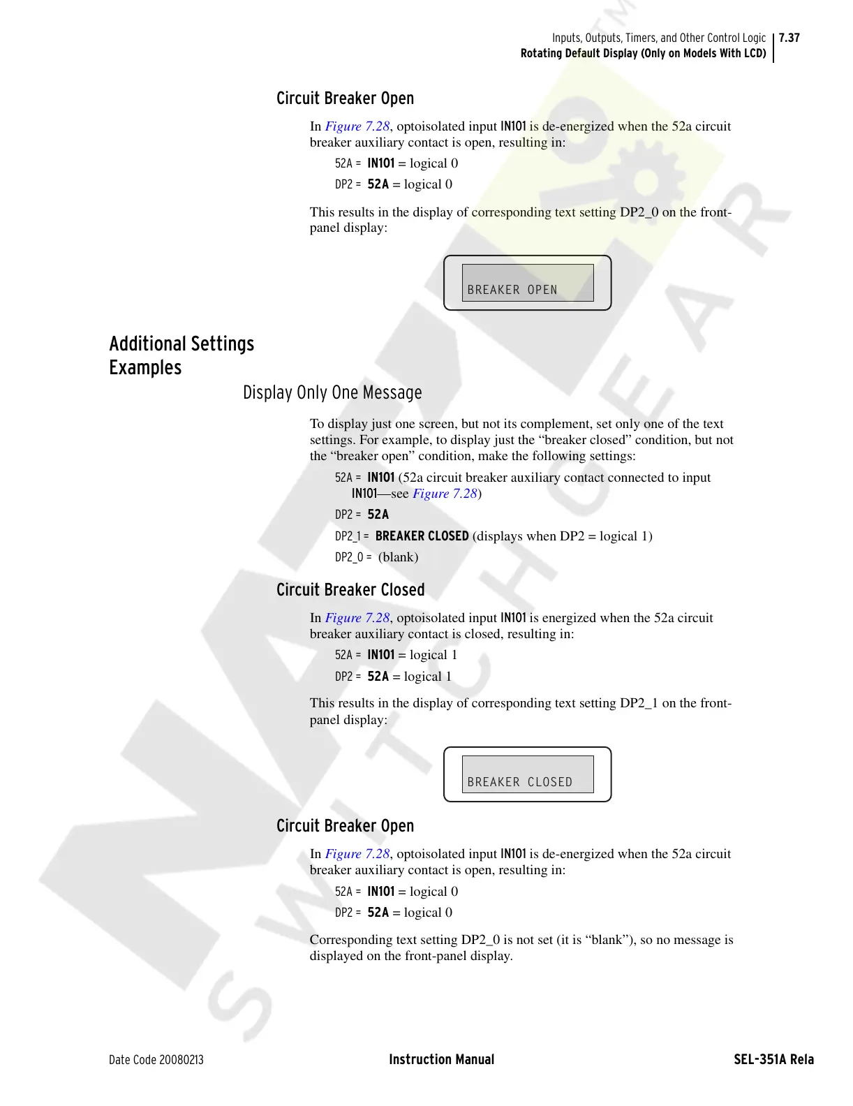
This results in the display of corresponding text setting DP2_0 on the front-
panel display:
Additional Settings
Examples
Display Only One Message
To display just one screen, but not its complement, set only one of the text
settings. For example, to display just the “breaker closed” condition, but not
the “breaker open” condition, make the following settings:
52A = IN101 (52a circuit breaker auxiliary contact connected to input
IN101—see Figure 7.28)
DP2 = 52A
DP2_1 = BREAKER CLOSED (displays when DP2 = logical 1)
DP2_0 = (blank)
Circuit Breaker Closed
In Figure 7.28, optoisolated input IN101 is energized when the 52a circuit
breaker auxiliary contact is closed, resulting in:
52A = IN101 = logical 1
DP2 = 52A = logical 1
This results in the display of corresponding text setting DP2_1 on the front-
panel display:
Circuit Breaker Open
In Figure 7.28, optoisolated input IN101 is de-energized when the 52a circuit
breaker auxiliary contact is open, resulting in:
52A = IN101 = logical 0
DP2 = 52A = logical 0
Corresponding text setting DP2_0 is not set (it is “blank”), so no message is
displayed on the front-panel display.
BREAKER OPEN
BREAKER CLOSED
Courtesy of NationalSwitchgear.com