7.39
Date Code 20080213 Instruction Manual SEL-351A Relay
Inputs, Outputs, Timers, and Other Control Logic
Rotating Default Display (Only on Models With LCD)
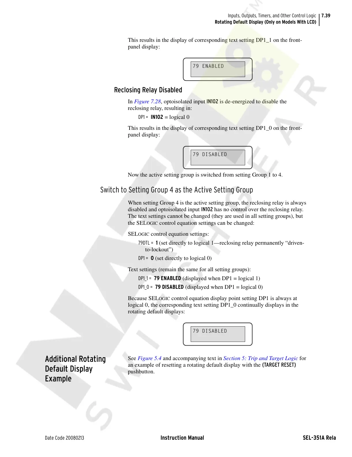
This results in the display of corresponding text setting DP1_1 on the front-
panel display:
Reclosing Relay Disabled
In Figure 7.28, optoisolated input IN102 is de-energized to disable the
reclosing relay, resulting in:
DP1 = IN102 = logical 0
This results in the display of corresponding text setting DP1_0 on the front-
panel display:
Now the active setting group is switched from setting Group 1 to 4.
Switch to Setting Group 4 as the Active Setting Group
When setting Group 4 is the active setting group, the reclosing relay is always
disabled and optoisolated input IN102 has no control over the reclosing relay.
The text settings cannot be changed (they are used in all setting groups), but
the SEL
OGIC control equation settings can be changed:
SEL
OGIC control equation settings:
79DTL = 1 (set directly to logical 1—reclosing relay permanently “driven-
to-lockout”)
DP1 = 0 (set directly to logical 0)
Text settings (remain the same for all setting groups):
DP1_1 = 79 ENABLED (displayed when DP1 = logical 1)
DP1_0 = 79 DISABLED (displayed when DP1 = logical 0)
Because SEL
OGIC control equation display point setting DP1 is always at
logical 0, the corresponding text setting DP1_0 continually displays in the
rotating default displays:
Additional Rotating
Default Display
Example
See Figure 5.4 and accompanying text in Section 5: Trip and Target Logic for
an example of resetting a rotating default display with the {TARGET RESET}
pushbutton.
79 ENABLED
79 DISABLED
79 DISABLED
Courtesy of NationalSwitchgear.com