9.31
Date Code 20080213 Instruction Manual SEL-351A Relay
Setting the Relay
Relay Word Bits (Used in SEL
OGIC Control Equations)
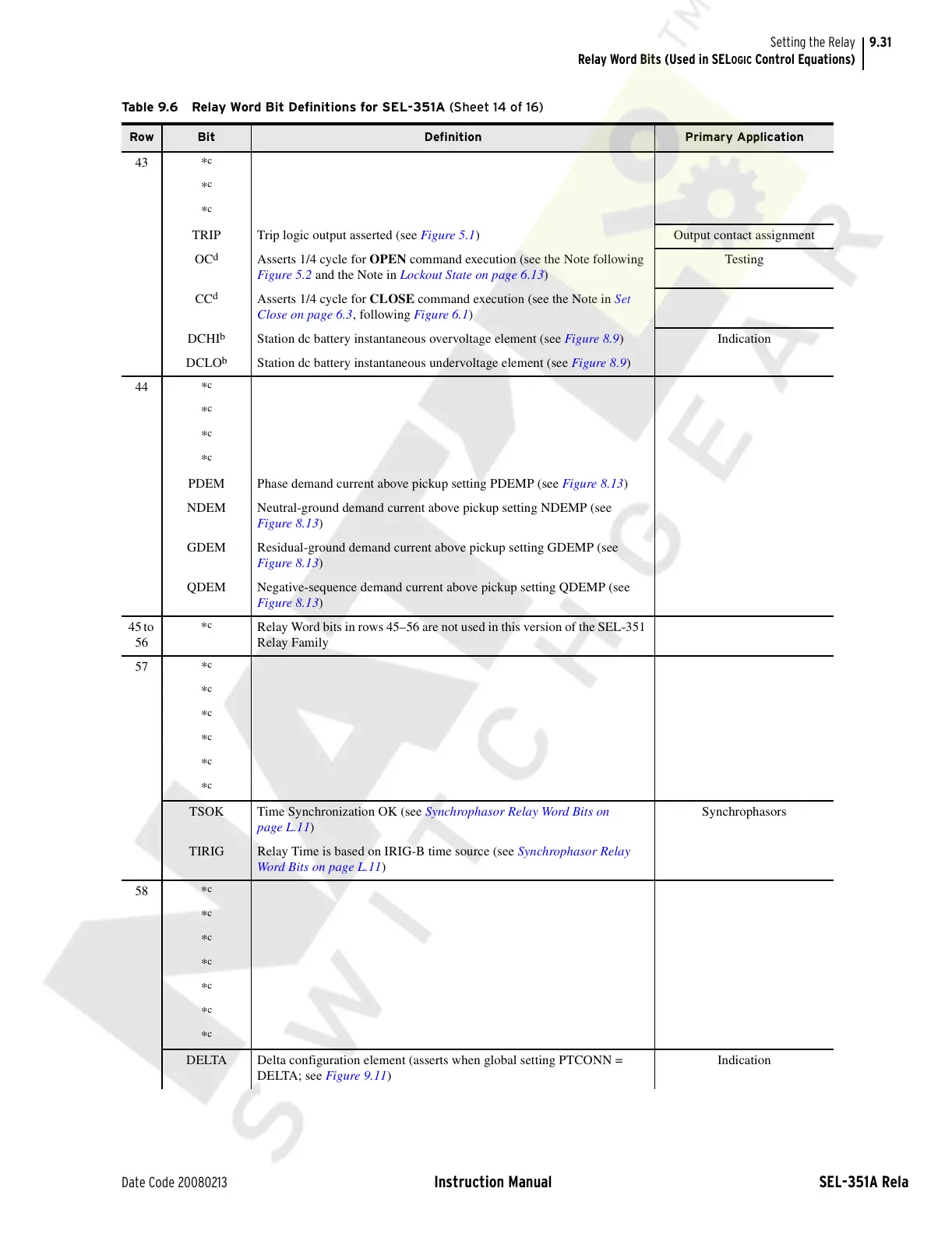
43 *
c
*
c
*
c
TRIP Trip logic output asserted (see Figure 5.1) Output contact assignment
OC
d
Asserts 1/4 cycle for OPEN command execution (see the Note following
Figure 5.2 and the Note in Lockout State on page 6.13)
Testing
CC
d
Asserts 1/4 cycle for CLOSE command execution (see the Note in Set
Close on page 6.3, following Figure 6.1)
DCHI
b
Station dc battery instantaneous overvoltage element (see Figure 8.9) Indication
DCLO
b
Station dc battery instantaneous undervoltage element (see Figure 8.9)
44 *
c
*
c
*
c
*
c
PDEM Phase demand current above pickup setting PDEMP (see Figure 8.13)
NDEM Neutral-ground demand current above pickup setting NDEMP (see
Figure 8.13)
GDEM Residual-ground demand current above pickup setting GDEMP (see
Figure 8.13)
QDEM Negative-sequence demand current above pickup setting QDEMP (see
Figure 8.13)
45 to
56
*
c
Relay Word bits in rows 45–56 are not used in this version of the SEL-351
Relay Family
57 *
c
*
c
*
c
*
c
*
c
*
c
TSOK Time Synchronization OK (see Synchrophasor Relay Word Bits on
page L.11)
Synchrophasors
TIRIG Relay Time is based on IRIG-B time source (see Synchrophasor Relay
Word Bits on page L.11)
58 *
c
*
c
*
c
*
c
*
c
*
c
*
c
DELTA Delta configuration element (asserts when global setting PTCONN =
DELTA; see Figure 9.11)
Indication
Table 9.6 Relay Word Bit Definitions for SEL-351A (Sheet 14 of 16)
Row Bit Definition Primary Application
Courtesy of NationalSwitchgear.com