9.33
Date Code 20080213 Instruction Manual SEL-351A Relay
Setting the Relay
Relay Word Bits (Used in SEL
OGIC Control Equations)
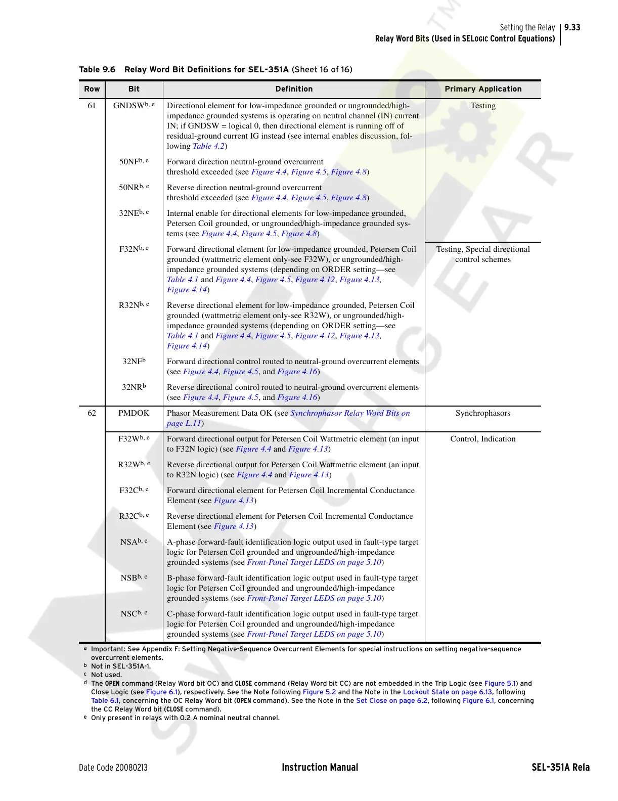
61 GNDSW
b, e
Directional element for low-impedance grounded or ungrounded/high-
impedance grounded systems is operating on neutral channel (IN) current
IN; if GNDSW = logical 0, then directional element is running off of
residual-ground current IG instead (see internal enables discussion, fol-
lowing Table 4. 2)
Testing
50NF
b, e
Forward direction neutral-ground overcurrent
threshold exceeded (see Figure 4.4, Figure 4.5, Figure 4.8)
50NR
b, e
Reverse direction neutral-ground overcurrent
threshold exceeded (see Figure 4.4, Figure 4.5, Figure 4.8)
32NE
b, e
Internal enable for directional elements for low-impedance grounded,
Petersen Coil grounded, or ungrounded/high-impedance grounded sys-
tems (see Figure 4.4, Figure 4.5, Figure 4.8)
F32N
b, e
Forward directional element for low-impedance grounded, Petersen Coil
grounded (wattmetric element only-see F32W), or ungrounded/high-
impedance grounded systems (depending on ORDER setting—see
Table 4 .1 and Figure 4.4, Figure 4.5, Figure 4.12, Figure 4.13,
Figure 4.14)
Testing, Special directional
control schemes
R32N
b, e
Reverse directional element for low-impedance grounded, Petersen Coil
grounded (wattmetric element only-see R32W), or ungrounded/high-
impedance grounded systems (depending on ORDER setting—see
Table 4 .1 and Figure 4.4, Figure 4.5, Figure 4.12, Figure 4.13,
Figure 4.14)
32NF
b
Forward directional control routed to neutral-ground overcurrent elements
(see Figure 4.4, Figure 4.5, and Figure 4.16)
32NR
b
Reverse directional control routed to neutral-ground overcurrent elements
(see Figure 4.4, Figure 4.5, and Figure 4.16)
62 PMDOK Phasor Measurement Data OK (see Synchrophasor Relay Word Bits on
page L.11)
Synchrophasors
F32W
b, e
Forward directional output for Petersen Coil Wattmetric element (an input
to F32N logic) (see Figure 4.4 and Figure 4.13)
Control, Indication
R32W
b, e
Reverse directional output for Petersen Coil Wattmetric element (an input
to R32N logic) (see Figure 4.4 and Figure 4.13)
F32C
b, e
Forward directional element for Petersen Coil Incremental Conductance
Element (see Figure 4.13)
R32C
b, e
Reverse directional element for Petersen Coil Incremental Conductance
Element (see Figure 4.13)
NSA
b, e
A-phase forward-fault identification logic output used in fault-type target
logic for Petersen Coil grounded and ungrounded/high-impedance
grounded systems (see Front-Panel Target LEDS on page 5.10)
NSB
b, e
B-phase forward-fault identification logic output used in fault-type target
logic for Petersen Coil grounded and ungrounded/high-impedance
grounded systems (see Front-Panel Target LEDS on page 5.10)
NSC
b, e
C-phase forward-fault identification logic output used in fault-type target
logic for Petersen Coil grounded and ungrounded/high-impedance
grounded systems (see Front-Panel Target LEDS on page 5.10)
a
Important: See Appendix F: Setting Negative-Sequence Overcurrent Elements for special instructions on setting negative-sequence
overcurrent elements.
b
Not in SEL-351A-1.
c
Not used.
d
The OPEN command (Relay Word bit OC) and CLOSE command (Relay Word bit CC) are not embedded in the Trip Logic (see Figure 5.1) and
Close Logic (see Figure 6.1), respectively. See the Note following Figure 5.2 and the Note in the Lockout State on page 6.13, following
Ta bl e 6 .1 , concerning the OC Relay Word bit (OPEN command). See the Note in the Set Close on page 6.2, following Figure 6.1, concerning
the CC Relay Word bit (CLOSE command).
e
Only present in relays with 0.2 A nominal neutral channel.
Table 9.6 Relay Word Bit Definitions for SEL-351A (Sheet 16 of 16)
Row Bit Definition Primary Application
Courtesy of NationalSwitchgear.com