Date _______________
Date Code 20080213 Instruction Manual SEL-351A-1 Relay
SET.15
of 26
SEL-351A-1 Settings Sheets
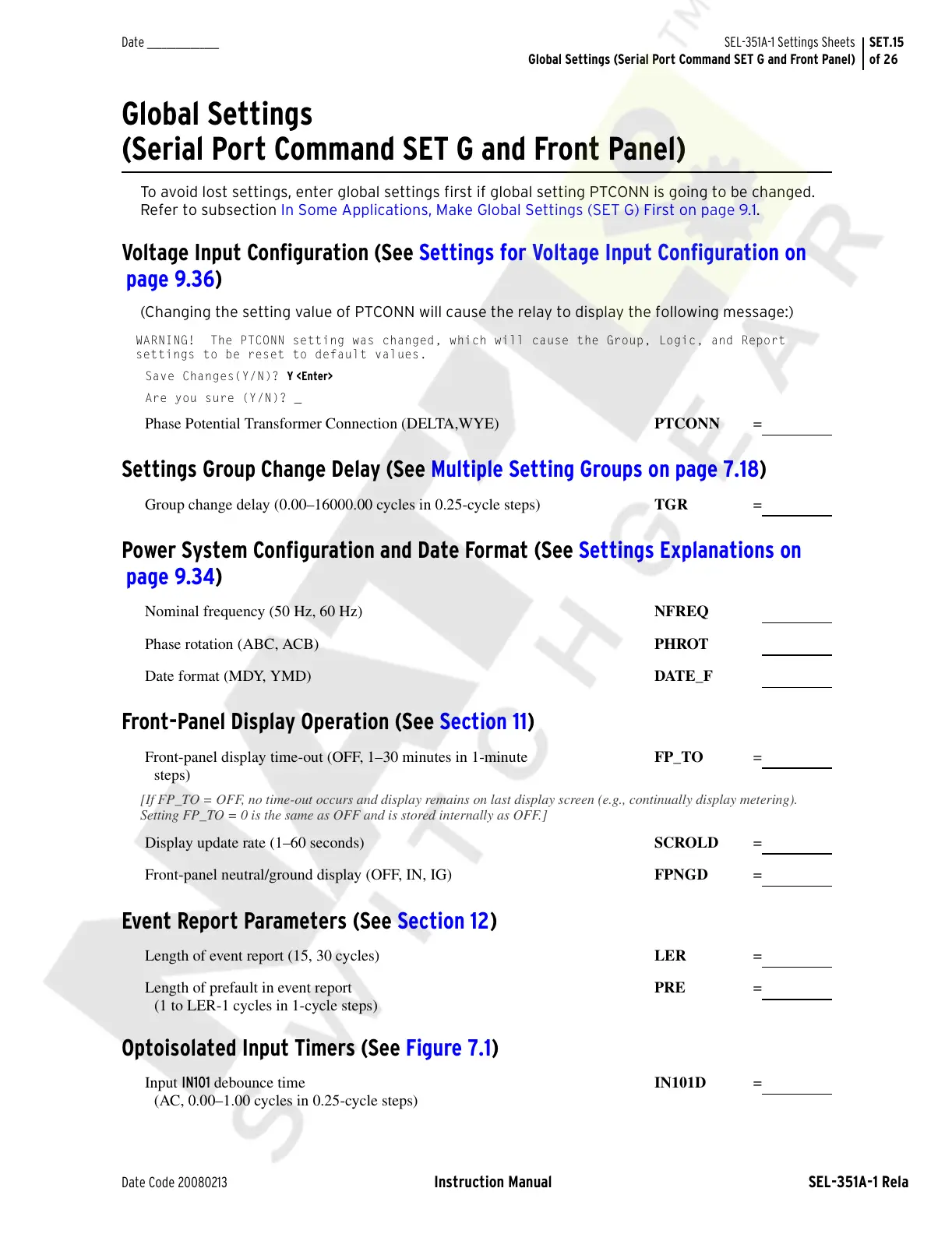
Global Settings (Serial Port Command SET G and Front Panel)
Global Settings
(Serial Port Command SET G and Front Panel)
To avoid lost settings, enter global settings first if global setting PTCONN is going to be changed.
Refer to subsection In Some Applications, Make Global Settings (SET G) First on page 9.1.
Voltage Input Configuration (See Settings for Voltage Input Configuration on
page 9.36)
(Changing the setting value of PTCONN will cause the relay to display the following message:)
WARNING! The PTCONN setting was changed, which will cause the Group, Logic, and Report
settings to be reset to default values.
Save Changes(Y/N)? Y <Enter>
Are you sure (Y/N)? _
Phase Potential Transformer Connection (DELTA,WYE) PTCONN =
Settings Group Change Delay (See Multiple Setting Groups on page 7.18)
Group change delay (0.00–16000.00 cycles in 0.25-cycle steps) TGR =
Power System Configuration and Date Format (See Settings Explanations on
page 9.34)
Nominal frequency (50 Hz, 60 Hz) NFREQ
Phase rotation (ABC, ACB)
PHROT
Date format (MDY, YMD)
DATE_F
Front-Panel Display Operation (See Section 11)
Front-panel display time-out (OFF, 1–30 minutes in 1-minute
steps)
FP_TO =
[If FP_TO = OFF, no time-out occurs and display remains on last display screen (e.g., continually display metering).
Setting FP_TO = 0 is the same as OFF and is stored internally as OFF.]
Display update rate (1–60 seconds) SCROLD =
Front-panel neutral/ground display (OFF, IN, IG)
FPNGD =
Event Report Parameters (See Section 12)
Length of event report (15, 30 cycles) LER =
Length of prefault in event report
(1 to LER-1 cycles in 1-cycle steps)
PRE =
Optoisolated Input Timers (See Figure 7.1)
Input IN101 debounce time
(AC, 0.00–1.00 cycles in 0.25-cycle steps)
IN101D =
Courtesy of NationalSwitchgear.com


 To Next Page