Section05FUELSYSTEM
Subsection 01 (CARBURETOR)
GENERAL
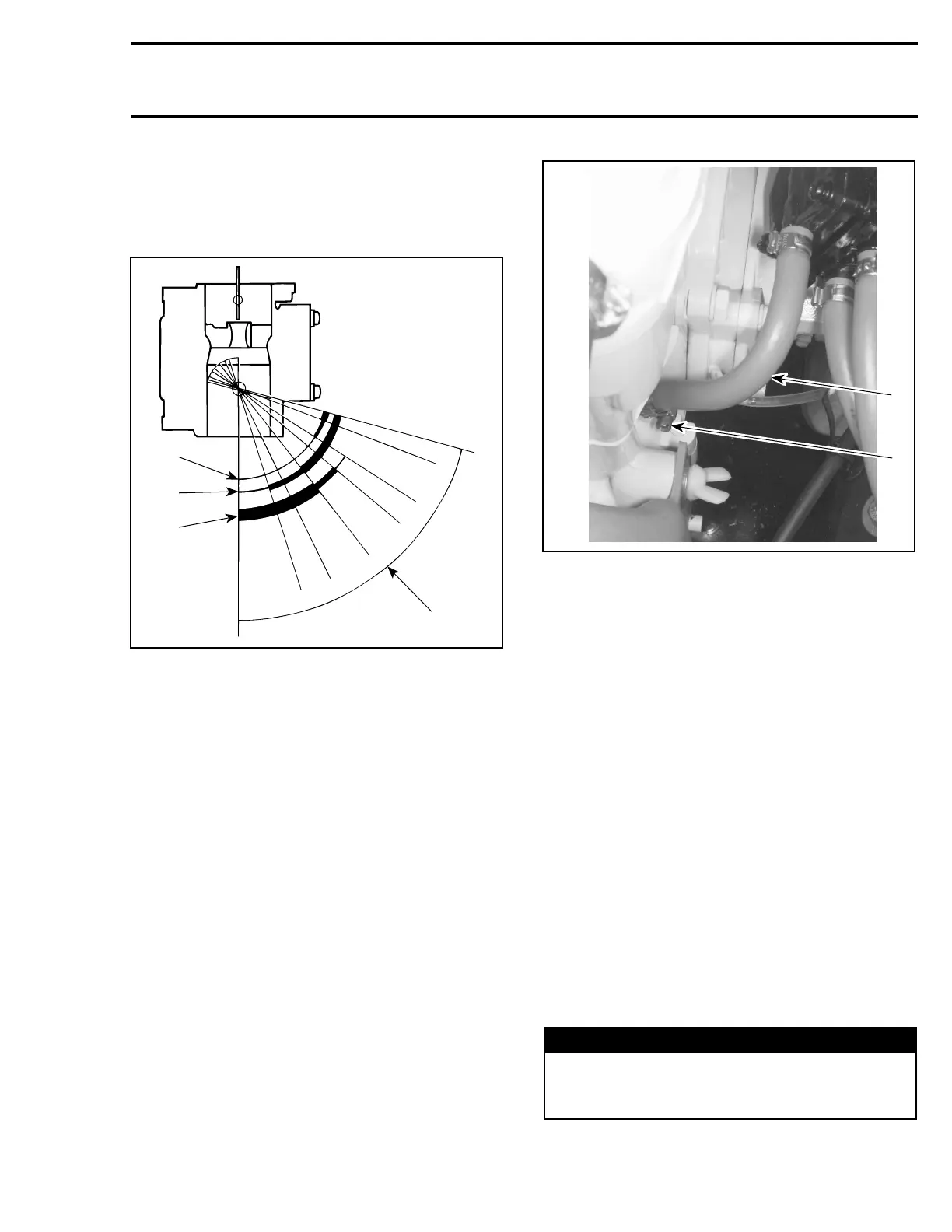
The following illustration shows which part of the
carburetor begins to function at different throttle
plate openings.
1
F01F13A
2
3
4
5
6
VIEW FROM AIR INTAKE OPENING
1. Throttle plate openings
2. Throttle plate closed
3. Throttle plate wide opened
4. Low-speed screw
5. Pilot jet
6. Main jet and high-speed screw
The carburetor is equipped with a fuel accelerator
pump.
The fuel accelerator pump is linked to the throttle
valve via a linkage.
A metering jet in the fuel inlet hose controls fuel
flow to the pump.
A check valve on the fuel outlet hose helps to
prime the system.
REMOVAL
To remove carburetor from engine, proceed as fol-
lows:
Remove air vent tube support.
Remove air intake silencer. Refer to AIR INTAKE.
Turn fuel valve to OFF position.
Disconnect pulse line.
F06F0LA
1
2
TYPICAL
1. Pulse line
2. Loosen gear clamp
Disconnect fuel supply line from fuel pump.
Disconnect fuel return line.
Disconnect oil injection pump cable, throttle cable
and choke cable.
Remove screws no. 1 and lock washers no. 2 re-
taining carburetor.
Remove carburetor.
CLEANING
The carburetor exterior surfaces should be
cleaned with a general solvent and dried with
compressed air before disassembly.
CAUTION: Be careful at carburetor cleaning not
to remove paint. Paint removal will cause car-
buretor to rust very rapidly. Repaint if neces-
sary.
Carburetor body and jets should be cleaned with
a carburetor cleaner. Follow manufacturer's in-
structions.
WARNING
Solvent with a low flash point such as gaso-
line, naphtha, benzol, etc., should not be used
as they are flammable and explosive.
smr2005-052 87