Section 11 HULL/BODY
Subsection 01 (GTI SERIES)
1
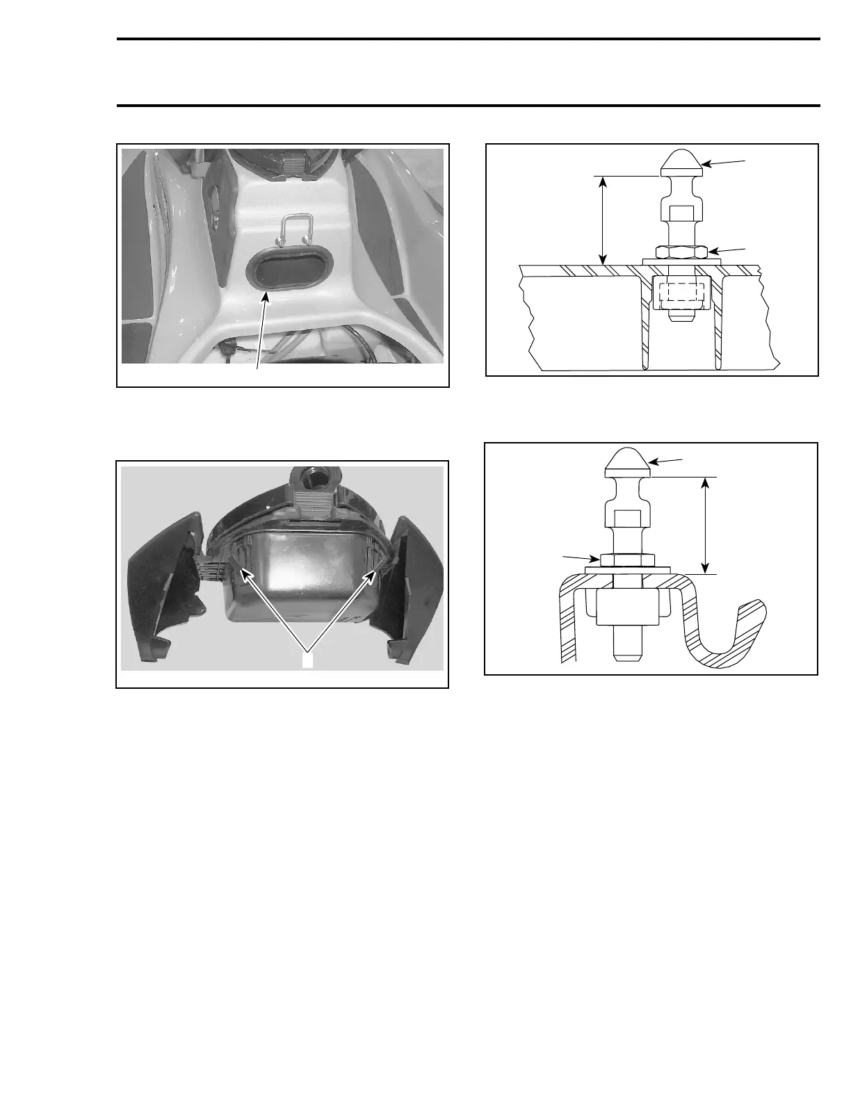
F16L0AA
1. Insert your hand here to release the lock tabs
From front storage compartment, pull glove box
out.
F16L0BA
1
1. Lock tabs
Installation
Reverse the removal procedure.
SEAT
Adjustment
NOTE: Apply Loctite 243 (blue) (P/N 293 800 060)
on threads of lock pin when the adjustment is re-
quired or when the lock pin is removed then rein-
stalled. The threads on new lock pin are coated
with a self-locking product, do not apply Loctite
243onthreads.
A
2
F17L0PA
1
FRONT SEAT
1. Lock pin
2. Adjustment nut (apply Loctite 243). Torque to 8 N•m(71lbf•
in)
A. 34 ± 1 mm (1-11/32 ± 3/64 in)
A
2
F17L0QA
1
REAR SEAT
1. Lock pin
2. Adjustment nut (apply Loctite 243). Torque to 8 N•m(71lbf•
in)
A. 34 ± 1 mm (1-11/32 ± 3/64 in)
STORAGE COMPARTMENT
INNER SHELL
Removal
To remove inner shell no. 6, proceed as follows:
CAUTION: Failure to follow this order may lead
to damaging inner plastic studs.
Remove retaining screws no. 7.
Gently pull on large end (rear end) and pull apart
towards the small end (front). See illustration.
smr2005-069 321