Section09PROPULSION
Subsection 02 (DRIVE SYSTEM)
GENERAL
Jet pump must be removed to replace any com-
ponents of the drive system. Refer to JET PUMP
for removal procedure.
REMOVAL
PTO Flywheel Guard
Lift and lock steering pole, remove engine cover
and storage tray.
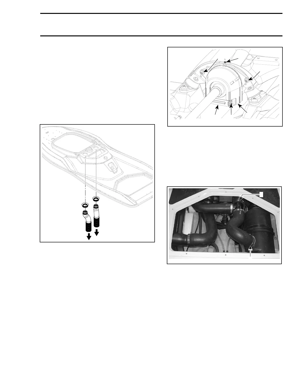
Pull down vent tubes from body.
F22J0AA
Detach link plate no. 1 at the back of flywheel
guard no. 2 then remove guard. The link plate
is held with 2 hexagonal bolts M6 no. 3 and the
flywheel with 2 wing nuts no. 4 andonthetop
with an hexagonal screw no. 5.
1
3
2
4
5
4
smr2005-063-003_a
1. Link plate
2. Flywheel guard
3. Link plate bolt
4. Wing nuts
5. Flywheel guard bolt
Circlip and Floating Ring
Remove the rear access panel.
Remove clamps from exhaust hoses where
shown.
F22D06A
1
1
1. Disconnect those clamps
Pull out T-fitting with hoses and resonator.
Moveremaininghoseawaytomakeroom.
Hold floating ring no. 6 and compress boot no. 7;
then, pull out circlip no. 8 from drive shaft groove.
smr2005-063 259