Section 04 LUBRICATION SYSTEM
Subsection 02 (OIL INJECTION PUMP)
F01D4SA
1
1
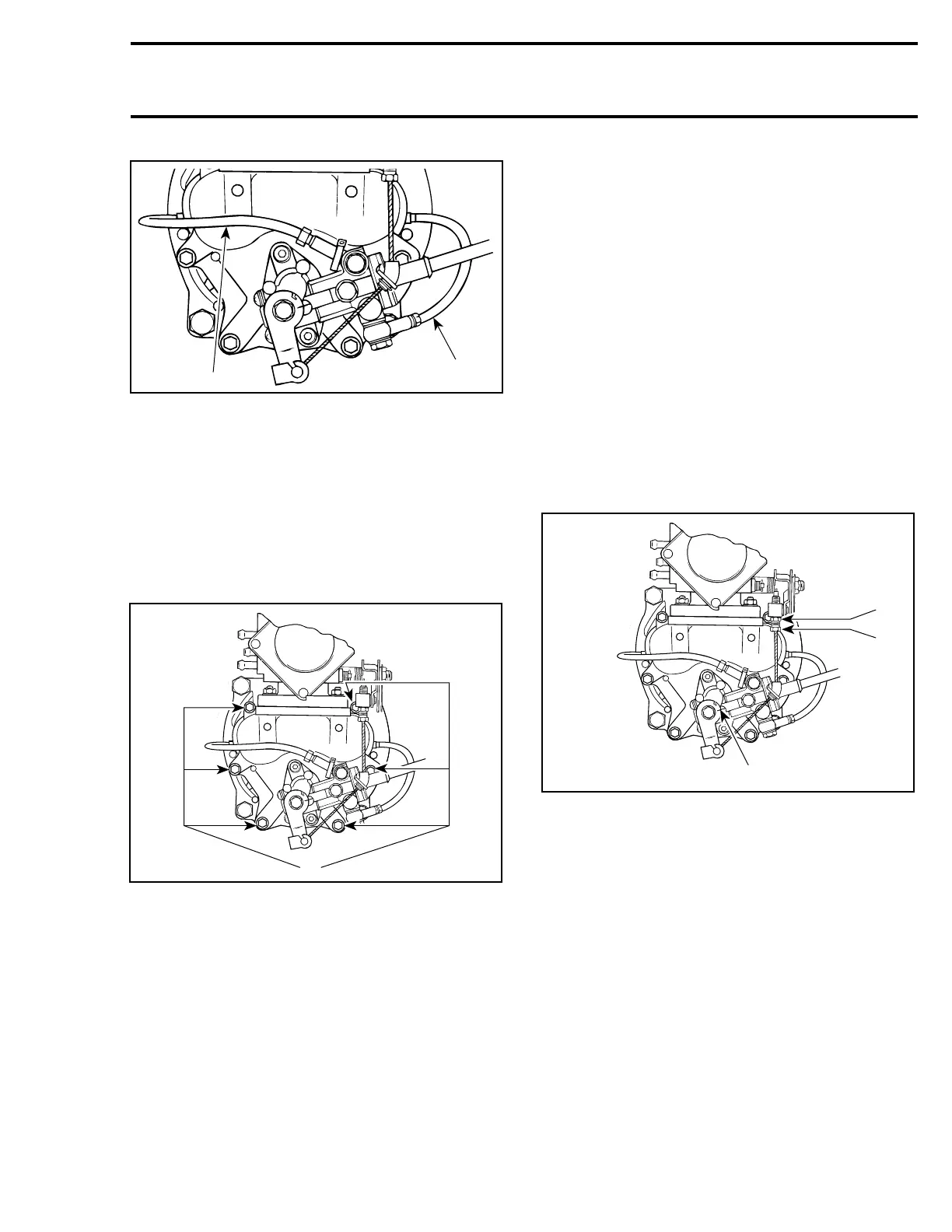
TYPICAL
1. Small oil line
Oil Pump Gear
Install gear no. 3 to oil injection pump shaft.
Torque lock nut no. 4 to 4.5 N•m(40lbf•in).
NOTE: Make sure 1 washer is installed on each
side of gear.
Install intake manifold no. 2 to rotary valve cover
and torque screws no. 5 to 10 N•m(89lbf•in).
F01D4RC
A
TYPICAL
A. 10 N•m(89lbf•in)
787 RFI Engines
Oil Injection Pump and Shaft
Make sure shaft no. 8 is installed in crankshaft
end. Apply Loctite anti-seize lubricant (P/N 293
800 070) on the end of shaft.
Install pump. Secure with flat washers and
screws no. 6. Torque to 6 N•m(53lbf•in).
Install oil injection pump cable.
ADJUSTMENT
CAUTION: As oil injection pump adjustment
is dependent on throttle cable position, make
sure to perform throttle cable adjustment first
except if otherwise specified.
Preliminary Synchronization
NOTE: To check synchronization of pump as a
routine maintenance, see FINAL SYNCHRONIZA-
TION.
Adjust throttle cable. Refer to CARBURETOR
(717 engines) or ENGINE MANAGEMENT (787
RFI engines).
Turn oil pump cable adjustment nut to align refer-
ence marks on pump.
NOTE: A mirror may be used to facilitate this ver-
ification.
F01D4RE
2
3
1
TYPICAL — 717 ENGINES
1. Jam nut
2. Adjustment nut
3. Aligned marks
smr2005-051 81