Section 07 ELECTRICAL SYSTEM
Subsection 04 (INSTRUMENTS AND ACCESSORIES)
3D RFI Series
RESISTANCE
(
)
FLOAT HEIGHT
(bottom of float with
bottom of pump module) (mm)
4.8 ± 2.2 247 ± 5.0
17.8 ± 2.2 207 ± 5.0
27.8 ± 2.2 183 ± 5.0
37.8 ± 2.2 158 ± 5.0
47.8 ± 2.2 133 ± 5.0
57.8 ± 2.4 105 ± 5.0
67.8 ± 2.8 76 ± 5.0
77.8 ± 3.6 55 ± 5.0
89.8 ± 3.6 35.3 ± 5.0
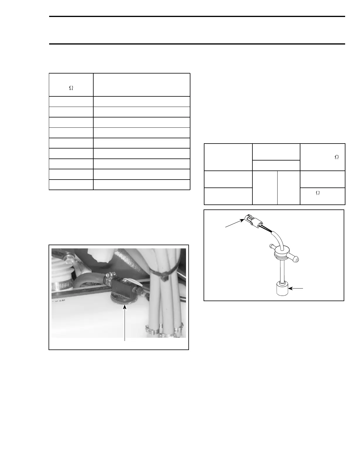
OIL SENSOR
All Models
The sensor circuit is either open (out of oil) or
closed (oil present) and the electronic module/
gauge turn lights ON or OFF accordingly.
F00H0LA
1
TYPICAL
1. Oil sensor
The bottom of the sensor has a small reservoir
withtwosmallholesunderneathtolettheoilen-
ter inside and one at the top to let the air enter
allowing the oil to flow out.
When there is enough oil inside the oil tank (and
therefore in the sensor reservoir), the sensor de-
tectstheliquidandthelightDOESNOTturnon.
When the oil level goes at critical LOW level inside
the oil tank (and therefore in sensor reservoir), the
sensor detects the absence of liquid and the light
TURNS ON.
Unplug sensor connector.
Using a multimeter, check the continuity as per
table.
NOTE: Wait about 15 - 20 seconds before taking
any reading to give the oil enough time to flow out
or inside sensor reservoir.
SENSOR
CONNECTOR
TEST
CONDITION
PIN
READING ( )
Sensor OUT
of oil
∞ (open circuit)
Sensor soaked
IN oil
A B
2 max.
(closed circuit)
F03H0BA
1
2
1. Measure resistance here
2. Sensor reservoir
Sensor Installation
– Remove rubber seal from sensor.
– Install seal in oil tank hole.
– Push sensor in seal.
– Plug connector.
NOTE: This sensor turns the LED to ON if the
connector has been forgotten unconnected.
smr2005-060 209