Section09PROPULSION
Subsection 02 (DRIVE SYSTEM)
REMOVAL
PTO Flywheel Guard
Remove seats.
Remove seat support.
Remove plastic wing nuts no. 4 retaining PTO fly-
wheel guard no. 5 to engine support.
Detach PTO flywheel guard from engine and with-
draw from bilge.
Circlip and Floating Ring
Hold floating ring no. 6 and compress boot no. 7;
then, pull out circlip no. 8 from drive shaft groove.
F06I06A
1 2
TYPICAL
1. Push floating ring
2. Remove circlip
Drive Shaft
Pull out drive shaft no. 9.
NOTE: If the drive shaft is jammed into PTO fly-
wheel, it may be necessary to remove PTO fly-
wheel from engine to then remove drive shaft.
Boot
Loosen gear clamp no. 10 holding boot no. 7,then
carefully pull boot and carbon ring no. 11 from hull
insert.
Carbon Ring
Loosen gear clamp no. 12 then pull carbon ring
no. 11 from boot no. 7.
INSPECTION
Drive Shaft
Inspect condition of drive shaft and PTO flywheel
splines.
Inspect condition of groove.
With your finger nail, feel machined surface of
drive shaft. If any irregular surface is found, re-
new drive shaft.
F01I0FA
321
1. Surface condition
2. Groove condition
3. Splines condition
Excessive deflection could cause vibration and
damage to drive shaft splines, impeller, flywheel
or floating ring (seal carrier depending upon the
model).
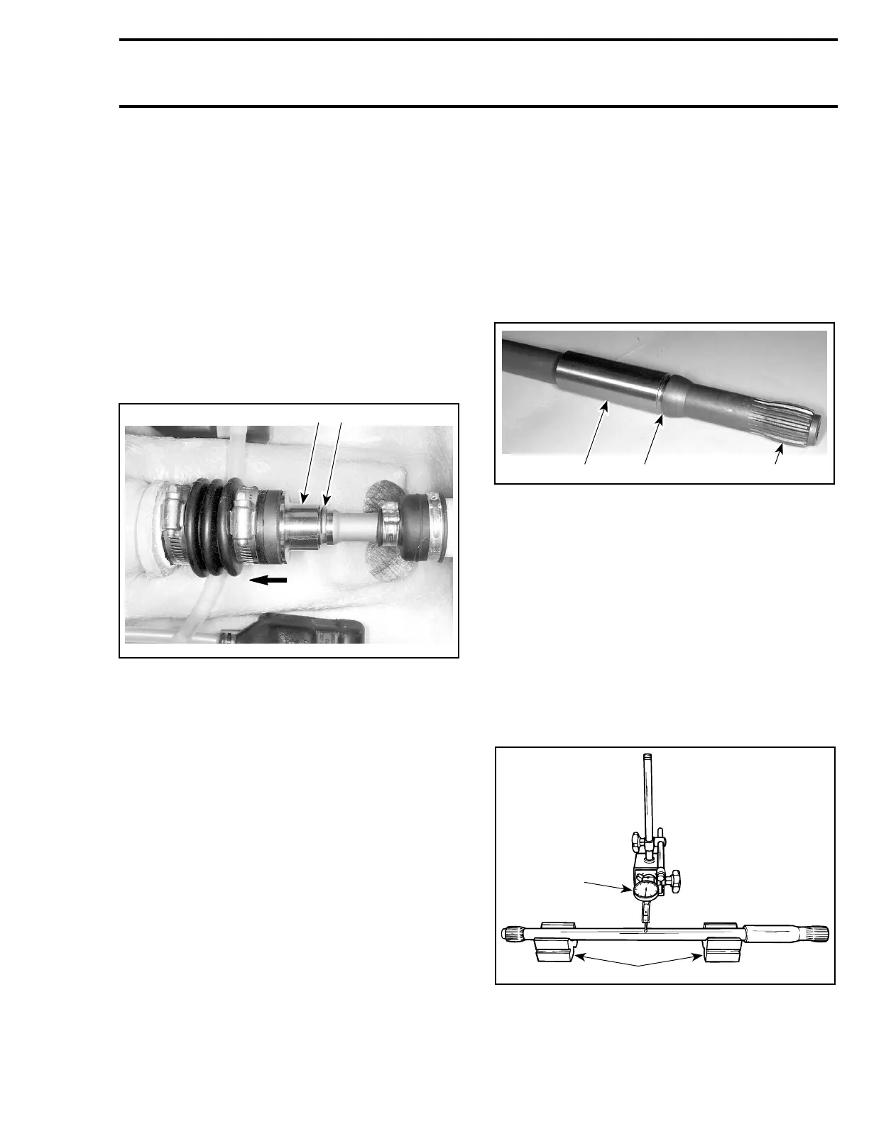
Place drive shaft on V-blocks and set-up a dial
gauge in center of shaft. Slowly rotate shaft; dif-
ference between highest and lowest dial gauge
reading is deflection. Refer to the following illus-
tration.
Maximum permissible deflection is 0.5 mm
(.020 in).
1
2
F01J15A
MEASURING DRIVE SHAFT DEFLECTION
1. Dial gauge
2. V-blocks
smr2005-063 255