Section07ELECTRICALSYSTEM
Subsection 01 (IGNITION SYSTEM)
Repeat armature plate positioning procedure if
timing mark position is not adequate.
TESTING PROCEDURES
When dealing with ignition problems, the follow-
ing items should be verified in this order:
1. Spark occurrence/spark plug condition.
2. Electrical connections.
3. Magneto output.
4. Multi-Purpose Electronic Module (MPEM).
5. Ignition coil output.
CAUTION: Whenever replacing a component in
ignition system, check ignition timing.
NOTE: To perform verifications, a good quality
multimeter such as Fluke 111 (P/N 529 035 868)
should be used.
529 035 868
SPARK PLUGS
Refer to TESTING PROCEDURES of the 787 RFI
engine further in this section.
GENERATING COIL
Static Test
Disconnect magneto wiring harness connector.
Install the 4-pin magneto harness adapter (P/N 295
000 131).
F01B28A
TYPICAL
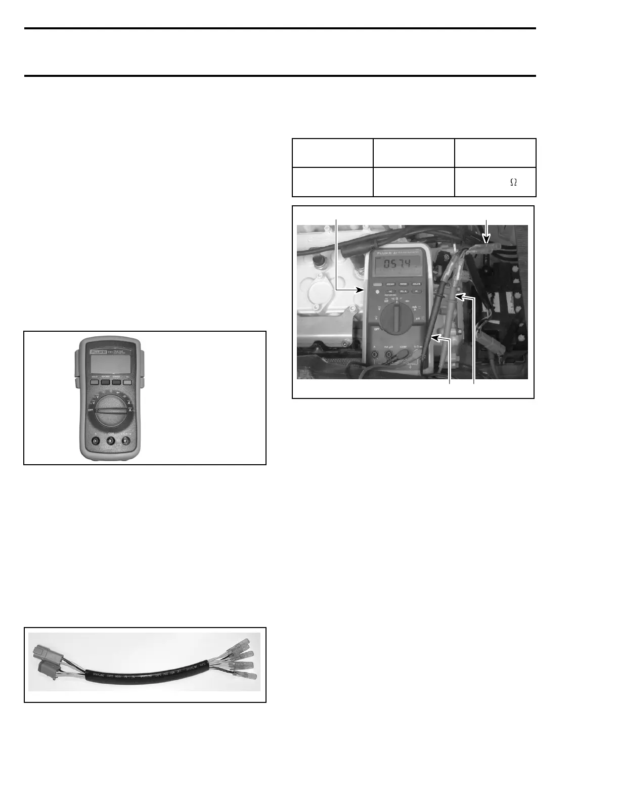
Check resistance with a multimeter. Refer to the
following table for values and wire colors.
PART NAME
ADAPTER
WIRE
RESISTANCE
Generating coil
BLACK with
RED/BLACK
40 - 76
F01H5WA
21
3
4
1. Multimeter
2. 4-pin magneto harness adapter
3. RED/BLACK wire
4. BLACK wire
Dynamic Test
1. Connect spark plug cables to grounding de-
vice.
2. Disconnect magneto wiring harness connec-
tor.
3. Install the 4-pin magneto harness adapter
(P/N 295 000 131).
4. Connect positive test probe of the multimeter
to the RED/BLACK wire of the 4-pin magneto
harness adapter.
5. Connect negative test probe of the multimeter
to BLACK wire of the 4-pin magneto harness
adapter.
6. Set multimeter to Vac scale.
7. Crank engine and note result. The obtained
valueshouldbebetween18and25Vac.
8. If the generating coil is out of specification,
replace it.
150 smr2005-057