Section 13 ELECTRICAL CONNECTORS AND WIRING DIAGRAMS
Subsection 01 (ELECTRICAL CONNECTORS)
WARNING
Ensure all terminals are properly crimped on
wires and connector are properly fastened.
AMP CONNECTOR
GTI Series with 717 Engine
These connectors are found on the MPEM.
When servicing electrical system, special care
must be taken when working with AMP connec-
tors in order to prevent any malfunction of the
system.
Description
F00H0WB
2
3
4
5
6
7
8
9
9
1
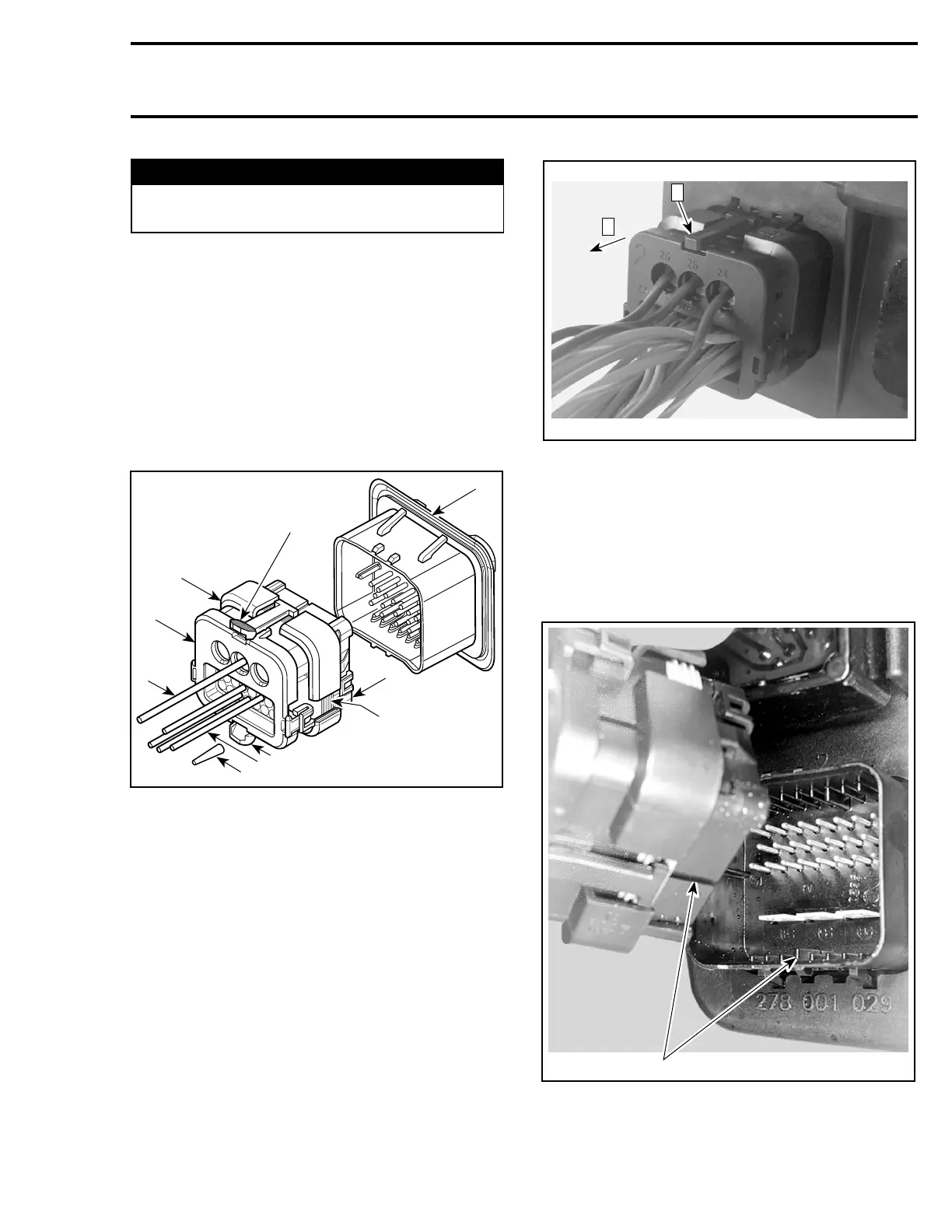
AMP CONNECTOR
1. Male connector
2. Cover assembly
3. Mating seal
4. Wedge lock
5. MPEM connector
6. Seal plug
7. Power wire
8. Signal wire
9. Locking tab
Removal
To remove the male connector from the MPEM,
press both tabs and pull connector.
F00H0NA
1
2
Step 1: Press tabs (both sides)
Step 2: Pull male connector
Installation
Do not apply any product to the pins of the con-
nectors on the MPEM.
Each male connector is mechanically keyed to
mate only with identical mechanical keyed con-
nector on the MPEM.
F00H12A
1
1. Mechanically keyed
smr2005-073 363