Section 07 ELECTRICAL SYSTEM
Subsection 03 (STARTING SYSTEM)
F01H0UA
2
1
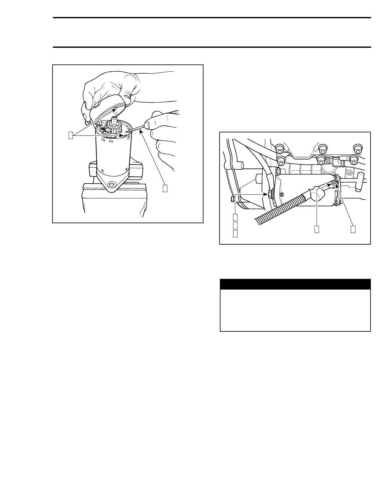
Step 1: Retaining brush holder with a screwdriver
Step 2: Align here
Align end frame notch with brush holder
notch/yoke protrusion.
CAUTION: Make sure end frame fits perfectly
on yoke.
INSTALLATION
Starter
Installation is essentially the reverse of removal
procedure. However, pay particular attention to
the following.
Make sure that starter and engine mating surfaces
are free of debris. Serious trouble may arise if
starter is not properly aligned.
Starter Retaining Screws
Apply service products as per the exploded view
given at the beginning of the section, on threads
and torque starter screws no. 13 and no. 16 to
22 N•m(16lbf•ft).
RED Positive Cable Retaining Nut
Connect the RED positive cable to the starter and
torque nut no. 17 to 6 N•m(53lbf•in). Apply
dielectric grease (P/N 293 550 004) on terminal
and nut.
BLACK Negative Cable Retaining Screw
and Teeth Washer
Apply Loctite 271 (P/N 293 800 005) to screw.
Connect BLACK negative cable to starter using
flat washer, teeth washer no. 15 and screw
no. 14. Torque screw to 22 N•m(16lbf•ft). Ap-
ply dielectric grease (P/N 293 550 004) on terminal
and screw.
F01H1JC
1 4
2
3
4
717 ENGINE SHOWN
Step 1: Torque nut to 6 N•m(53lbf•in)
Step 2: Apply Loctite 271 on screw
Step 3: Torque screw to 22 N•m(16lbf•ft)
Step 4: Apply dielectric grease
WARNING
Always connect RED positive cable first then
BLACK negative cable last. Whenever con-
necting the RED positive cable to the starter
motor make sure the battery cables are dis-
connected to prevent electric shock.
smr2005-059 193