Section07ELECTRICALSYSTEM
Subsection 01 (IGNITION SYSTEM)
smr2005-057-015
You should hear the spark occurring. In doubt, use
an inductive spark tester or a sealed tester — avail-
able from tool suppliers — to prevent spark occur-
ring in the bilge. If there is no spark, perform the
following checks.
NOTE: Keep in mind that even if there is a spark
during this static test, voltage requirement is high-
er to produce a spark in the combustion chamber
when engine is running. Ignition coil could be not
working in real operation. Replacing ignition coil
may be necessary as a test.
Resistance Test
Primary Side
An ignition coil with good resistance measure-
ment can still be faulty. Voltage leak can occur
at high voltage level which is not detectable with
an ohmmeter. Replacing the ignition coil may be
necessary as a test.
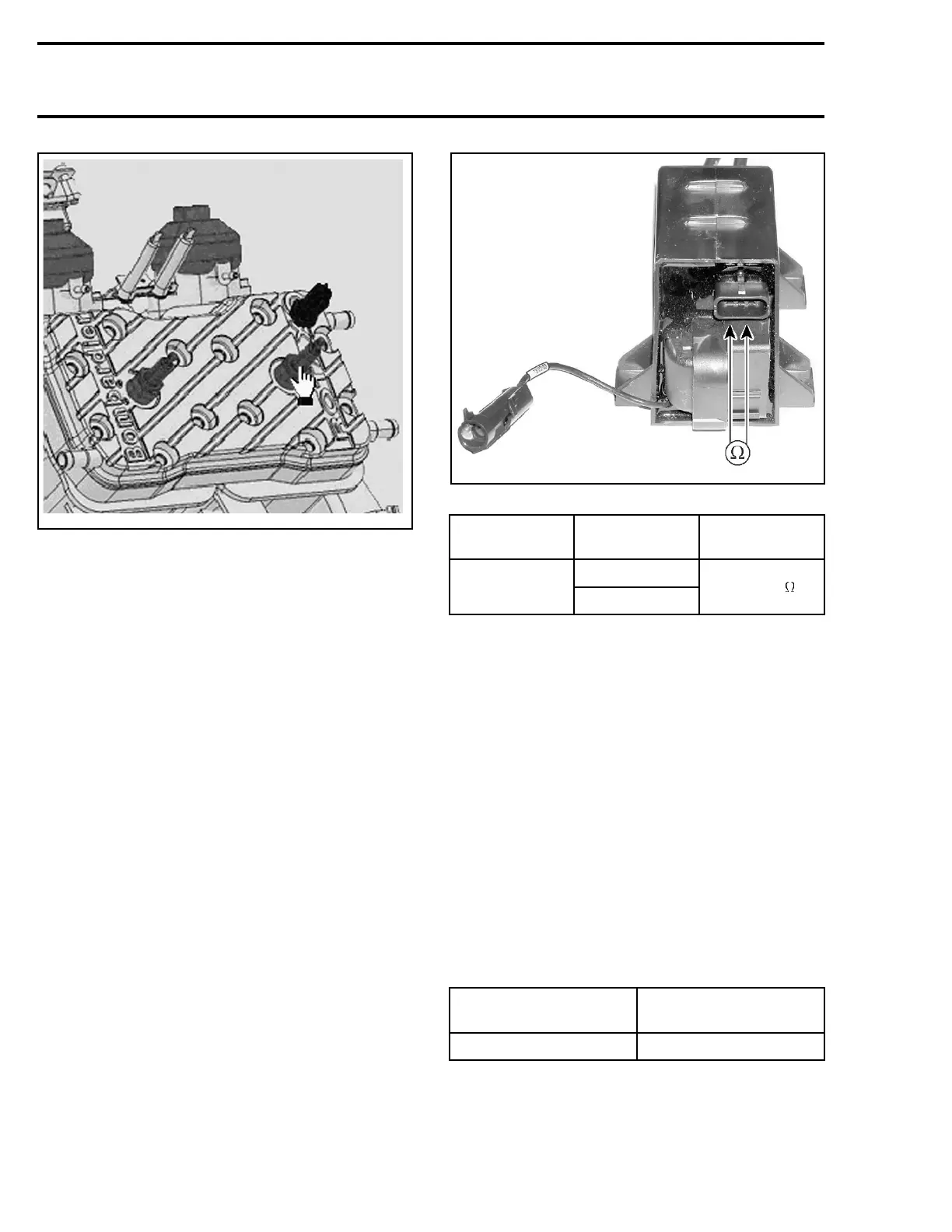
Using a multimeter, check the resistance in prima-
ry windings.
smr2005-057-018
PRIMARY CIRCUIT
CIRCUIT TERMINAL
RESISTANCE
@20°C(68°F)
1and2
Primary
2and3
0.3 - .6
If any resistance is not good, replace ignition coil.
Secondary Winding
Due to the integrated diode, it is not possible
to take any resistance measurement of the sec-
ondary winding.
VEHICLE CONTROL MODULE
(VCM)
Voltage Test
Verify the VCM output signal to the ignition coil as
follows:
Disconnect the 3-pin connector from the ignition
coil and check the voltage supplied by the VCM.
Install safety lanyard on the DESS post. Read volt-
age.
IGNITION COIL
CONNECTOR
VOLTAGE
Pin 2 with battery ground 12 V
160 smr2005-057