Section 06 ENGINE MANAGEMENT (RFI)
Subsection 03 (COMPONENT ADJUSTMENT, INSPECTION AND REPLACEMENT)
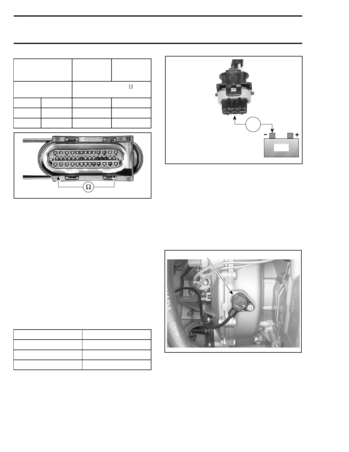
ECM CONNECTOR
THROTTLE
IDLE
POSITION
WIDE OPEN
THROTTLE
POSITION
PIN
RESISTANCE
@20°C(68°F)
A-24 A-25 2600 - 2700 710 - 1300
A-25 A-39 1600 - 2400 1600 - 2400
A-24 A-39 710 - 1300 2600 - 2700
smr2005-056-015_a
NOTE: The resistance value should change pro-
portionally to throttle movement. Otherwise, re-
place TPS.
If resistance values are correct, perform the VOLT-
AGE TEST below.
If resistance values are incorrect, check wiring har-
ness. If wiring is faulty, repair/replace. If wiring is
good, replace TPS.
Voltage Test
Check the ECM voltage output to the TPS.
Disconnect connector from TPS.
Remove and reinstall the safety lanyard to activate
the ECM.
Check the voltage readings from harness connec-
tor as follows.
TPS CONNECTOR VOLTAGE
Pin 1 with battery ground 0V
Pin 2 with battery ground 5V
Pin 3 with battery ground 4.5 - 5 V
BAT
Vdc
smr2005-056-016_a
If voltage test is not good, try a new ECM.
If voltage test is good, everything is in order.
THROTTLE BODY
Check that the throttle plate moves freely and
smoothly when depressing throttle lever. Verify
if throttle body is free of corrosion.
CRANKSHAFT POSITION
SENSOR (CPS)
F07H0CA
1
1. Crankshaft position sensor (CPS)
Resistance Test
Disconnect the A connector from the ECM.
Using a multimeter, check the resistance on the
ECM connector as per table.
136 smr2005-056