Section 10 STEERING SYSTEM
Subsection 03 (OFF-THROTTLE ASSISTED STEERING (O.T.A.S.))
Apply 12 V to the jumper wires. Solenoid should
pull on the throttle cable and hold it. Also try to
push on solenoid rod to make sure it is fully col-
lapsed.
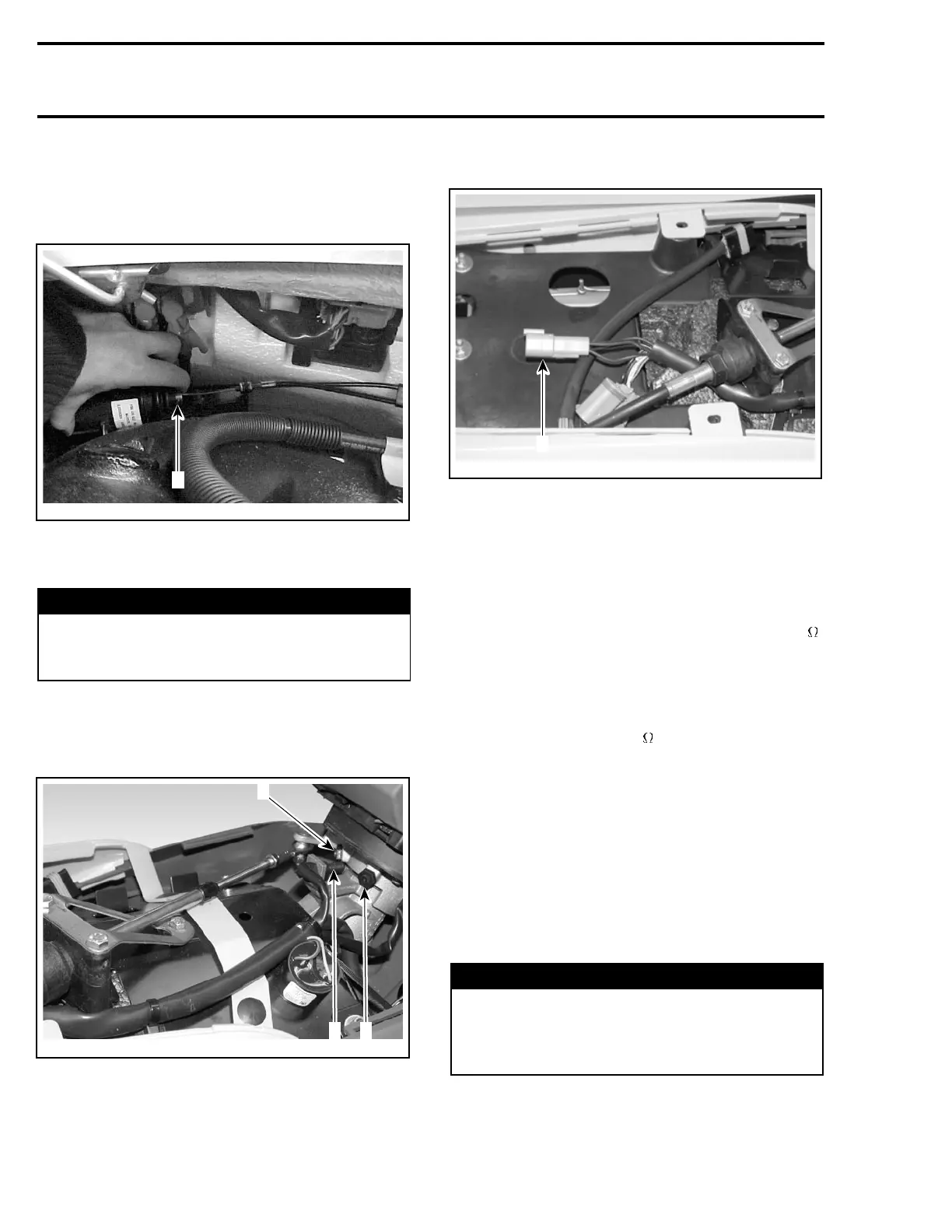
F22H0AA
1
1. Pushing on solenoid rod
If solenoid fails any test, replace solenoid.
WARNING
Whenever solenoid is replaced, ensure to per-
form throttle cable adjustment at the sole-
noid.
If solenoid tests good, proceed with the sensor
test.
Steering Position Switch
F22H0CA
1 2
2
1. Steering position switch
2. Magnet
Remove steering pole cover. Refer to BODY sec-
tion.
Disconnect the switch 4-pin connector.
F22H0DA
1
1. 4-pin connector
Perform the following tests for left and right sides.
Using the multimeter FLUKE 111 (P/N 529
035 868), measure the resistance between the
BLACK/WHITE and BLACK wires of switch while
steering is roughly at its center position.
Resistance should be between 446.5 and 493.5
.
Otherwise, check wiring harness and if good, re-
place switch.
Turn steering until it is blocked by its stopper.
Keep steering in this position.
Resistance should be 82
.
Otherwise, try any magnet and bring it in front
of the switch. If resistance is now good, replace
magnet.
If both resistance tests are good, check wiring har-
ness and if good, try a new VCM.
Reinstall steering pole cover.
ADJUSTMENT
O.T.A.S. Cable
WARNING
Whenever solenoid or throttle cable has been
replaced, ensure to perform the O.T.A.S cable
adjustment. Strictly follow the described pro-
cedure.
312 smr2005-068