Section 07 ELECTRICAL SYSTEM
Subsection 02 (CHARGING SYSTEM)
TESTING PROCEDURES
NOTE: First, ensure that battery is in good condi-
tion prior to performing the following tests.
BATTERY
Refer to TESTING PROCEDURE of the 787 RFI
ENGINE further in this section for the battery ver-
ifications.
RECTIFIER/REGULATOR
Static Test (Continuity)
Due to internal circuitry, there is no static test avail-
able.
Dynamic Test
Current Test
Proceed with a current test as follows:
– Start engine.
– Lay an inductive ammeter on positive cable of
battery.
– Bringenginetoapproximately6000RPM.
Current reading should be approximately 4 am-
peres for the 717 engine. If not, check magneto
output prior to concluding that rectifier is faulty.
DC Voltage Test
Proceed with a voltage test as follows:
– Start engine.
– Connect a multimeter to battery posts. Set
multimeter to Vdc scale.
– Bringenginetoapproximately5500RPM.
If multimeter reads over 15 volts, regulator is de-
fective. Replace it.
NOTE: If it is continually necessary to add distilled
water to the battery, this indicates an over voltage
situation, requiring replacement of the rectifier/
regulator. If, on the other hand, the battery will not
stay charged, the problem can be any of the charg-
ing circuit components. If these all check good,
you would be accurate in assuming the problem
to be in the rectifier/regulator.
If there is no charging at the battery with the pre-
ceding voltage test, the following test can also be
performed.
Disconnect the connector housing of the rectifier/
regulator.
Using an appropriate terminal remover (Snap-on
TT600-4), remove the RED and BLACK wires from
the tab housing of the rectifier/regulator.
Reconnect the connector housing.
Connect the positive probe of a multimeter to the
REDwireandthenegativeprobetotheBLACK
wire.
Set multimeter to Vdc scale.
Start and rev engine to 3500 RPM. The obtained
value should be between 12 and 25 Vdc.
NOTE: If the rectifier/regulator is within the spec-
ification, either the MPEM or wiring harness
between the rectifier and battery is defective. If
the rectifier/regulator is out of specification and
the battery charging coil (or stator) test good, the
rectifier/regulator is defective.
BATTERY CHARGING COIL
Static Test
Continuity
– Disconnect the magneto wiring harness con-
nector.
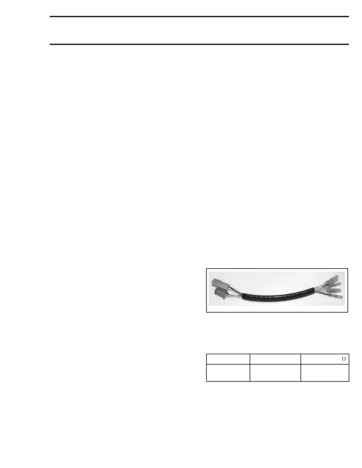
– Install the 4-pin magneto harness adapter
(P/N 295 000 131) to the magneto wiring har-
ness. Leave wiring harness side disconnected.
F01B28A
TYPICAL
– Check resistance between the YELLOW and
BLACK/YELLOW wires of the magneto harness
adapter. Refer to the following table.
PART NAME WIRE COLOR RESISTANCE
Battery
charging coil
YELLOW with
BLACK/YELLOW
0.05 - 0.6
NOTE: Ashortc
ircuit will read 0 ohm (or close to)
on ohmmeter
.
smr2005-058 167