Section 09 PROPULSION
Subsection 02 (DRIVE SYSTEM)
Front Drive Shaft
Install front drive shaft no. 13.
Rear Drive Shaft
NOTE: Ensure the alignment washers are still
loose.
Install damper no. 24 to rear drive shaft no. 10.
Install drive shaft and jet pump at the same time.
Insert drive shaft through carbon ring no. 22 and
floating ring no. 6.
Insert drive shaft through seal carrier housing
no. 14 and into the coupler assembly. Be careful
not to damage seals.
CAUTION: When sliding the drive shaft
through seal carrier, the double lip seal can be
folded over. This would cause a seal carrier
bearing failure.
Ensure grease fitting no. 31 of seal carrier housing
is located on the top.
Apply Loctite 243 (blue) (P/N 293 800 060) on
studs and install nuts no. 16.
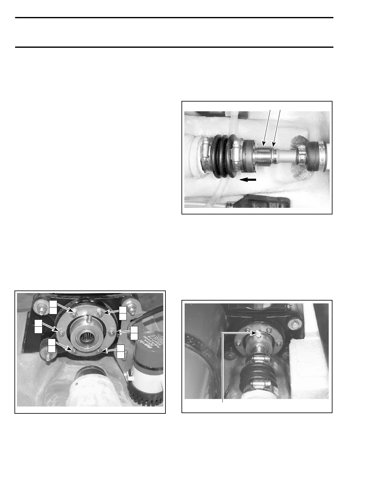
Refer to following illustration for tightening se-
quence. Torque 1 to 6 at 3 N•m(27lbf•in)and
then7to12at10N•m(89lbf•in).
NOTE: It is very important to tighten nuts of seal
carrier in this sequence to maintain its alignment.
F00B25B
9
4
7
2
11
6
10
3
8
1
12
5
TIGHTENING SEQUENCE
Reinstall shaft guard no. 9. Apply Loctite 243
(blue) (P/N 293 800 060) on bolts and torque lock
nuts to 10 N•m(89lbf•in).
Circlip
Push the floating ring no. 6 to compress the boot
no. 7. Insert the circlip no. 8 in the drive shaft
groove.
F06I06A
1 2
TYPICAL
1. Push floating ring
2. Insert circlip in the groove
Slide the floating ring onto the circlip.
LUBRICATION
Seal Carrier of Mid Bearing
Using a grease gun, lubricate seal carrier of mid
bearing with synthetic grease (P/N 293 550 010).
F05I09A
1
TYPICAL
1. Grease fitting
266 smr2005-063