Section 06 ENGINE MANAGEMENT (RFI)
Subsection 03 (COMPONENT ADJUSTMENT, INSPECTION AND REPLACEMENT)
Remove the air temperature sensor to ease re-
moval of the TPS.
Disconnect the TPS connector.
Loosen 2 Allen screws retaining the TPS.
Remove TPS.
NOTE: Resetting should be done using VCK each
time the TPS is loosened, removed or changed.
RefertoADJUSTMENTinthissection.
AIR TEMPERATURE SENSOR
(ATS)
Remove the air intake silencer.
Remove the flame arrester.
Disconnect the ATS the connector.
Pull the ATS from the grommet retaining it.
AIR PRESSURE SENSOR (APS)
Remove the air intake silencer.
Disconnect the APS connector.
Loosen Allen screw retaining the APS.
Remove the APS.
At installation, apply Loctite 243 (P/N 293 800 060)
on screw threads.
WATER TEMPERATURE
SENSOR (WTS)
Disconnect the WTS connector.
Loosen the WTS from the cylinder head.
At installation, apply Loctite 518 (P/N 293 800 038)
on threads of the WTS.
CRANKSHAFT POSITION
SENSOR (CPS)
Disconnect the CPS connector.
Loosen Allen screw retaining the CPS.
Remove the CPS.
At installation, ensure to reinstall shim between
crankcase and CPS.
smr2005-056-007
1. Shim under CPS
Apply Loctite 243 (P/N 293 800 060) on the Allen
screw.
NOTE: Clean threads prior to installing screw.
FUEL INJECTORS
Place a suitable container below the quick connect
fitting of the fuel rail.
Cover the quick connect fitting of the fuel rail with
a shop towel.
Press on both tabs and disconnect the quick con-
nect fitting.
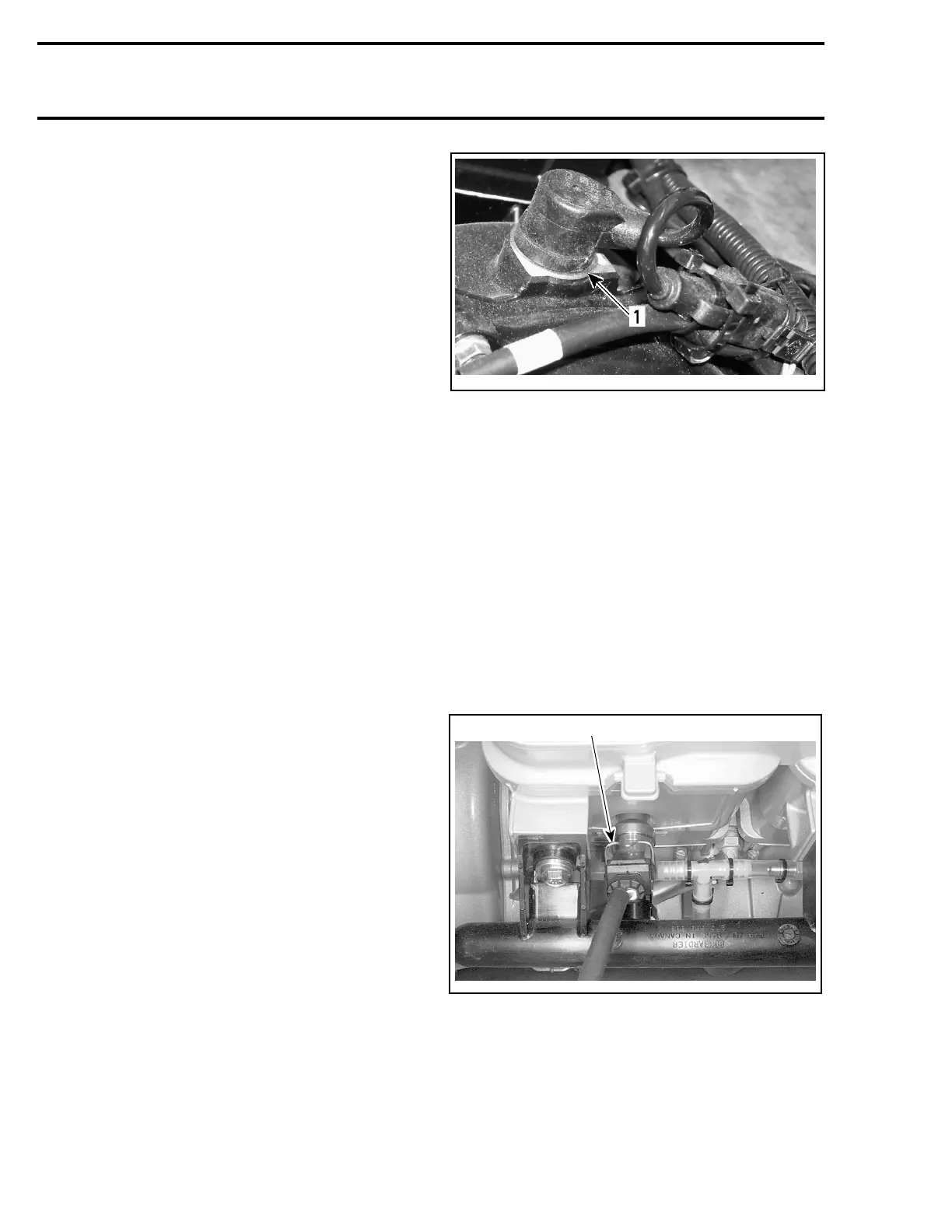
Disconnect the wire connectors of both fuel injec-
tors.
F07F0RA
1
1. Press retaining clip to unlock the connector
Loosen both screws retaining the fuel rail to the
cylinders.
142 smr2005-056