Section 08 COOLING SYSTEM
Subsection 01 (COMPONENTS AND CIRCUIT)
F06L0GA
max. 90°
TYPICAL
Technical Data
TYPE
TLCS (Total Loss Cooling
System).
COOLANT FLOW Flow from impeller
housing (no water
pump).
TEMPERATURE
CONTROL
Calibrated outlet fittings
(no thermostat).
SYSTEM BLEEDING
Self-bleed type (hose
at uppermost point of
circuit).
SYSTEM DRAINING
Self-drain type (hose at
lowest point of circuit).
SYSTEM FLUSHING Fitting hose adapter.
MONITORING BEEPER
Turnsonat86-94°C
(187 - 201°F).
COMPONENTS
Temperature Sensor
NOTE: This procedure must be used with 717 en-
gines only. For the 787 RFI engines, refer to EN-
GINE MANAGEMENT (RFI).
The temperature sensor is located on the top of
cylinder head.
smr2005-061-003_A
1. Temperature sensor
To test the sensor, unplug and remove it from en-
gine.
Put in water and heat water.
The temperature sensor should operate when wa-
ter temperature reaches 90° C±4° C(194° F±39°
F). Replace as necessary.
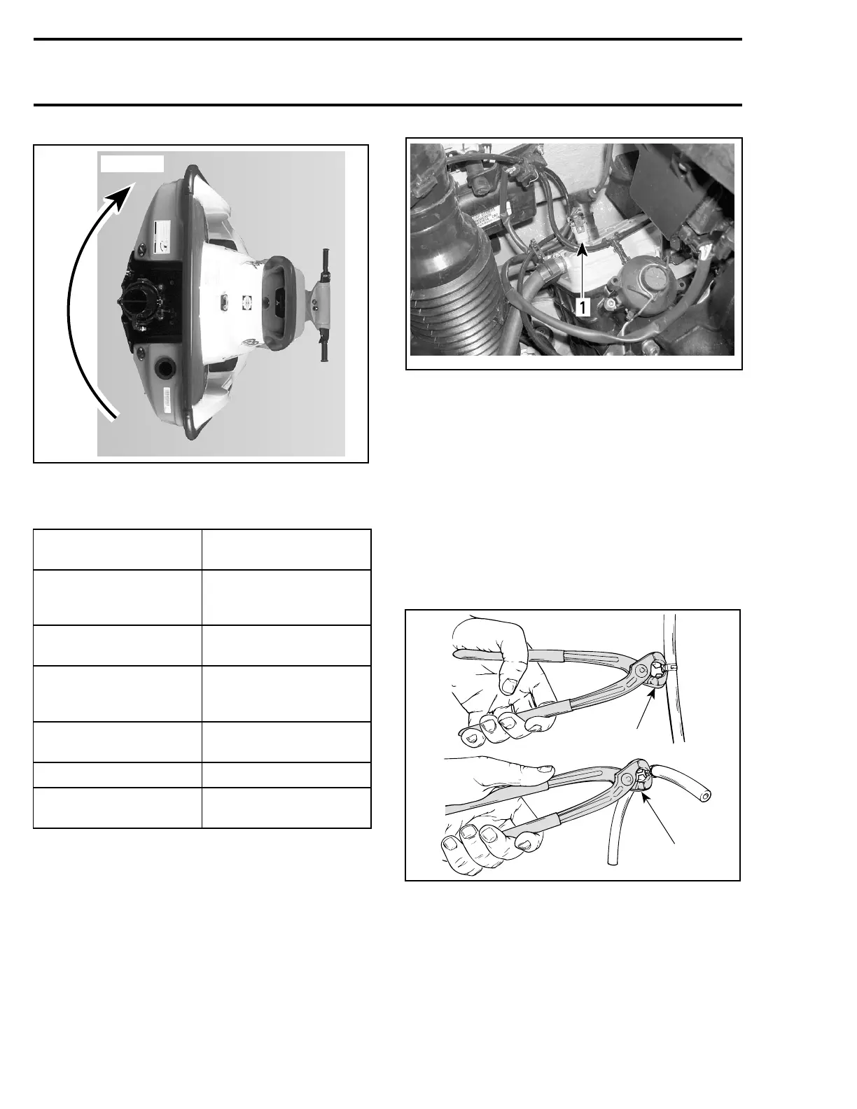
Clamp
To cut or secure non-reusable Oetiker clamps of
cooling system hoses, use the pliers Oetiker 1099
(P/N 295 000 070).
1
F01B2KA
2
1. Cutting clamp
2. Securing clamp
228 smr2005-061