Section07ELECTRICALSYSTEM
Subsection 03 (STARTING SYSTEM)
REMOVAL
Starter
Disconnect BLACK cable ground connection from
battery.
WARNING
Always disconnect ground cable first and re-
connect last.
Disconnect RED cable connection from battery.
Remove the following parts:
– cables from starter
– screw no. 13 of starter rear support
– starter mount screws no. 16.
DISASSEMBLY
Starter
Before disassembling, trace index marks on yoke
no. 1 andclutchhousingno. 10 to ease further
assembly.
F01H0PA
1
TYPICAL
1. Trace indexing marks
Remove starter support nuts no. 12 then through
bolts no. 5. Separate end frame no. 3 from yoke
assembly no. 1. Withdraw yoke assembly from
armature no. 11.
Brush holder no. 2 can be removed from end
frame no. 3 by unscrewing nut retaining terminal.
Check that the radial play between the armature
shaft and end frame is not greater than 0.20 mm
(.008 in). Replace end frame if so.
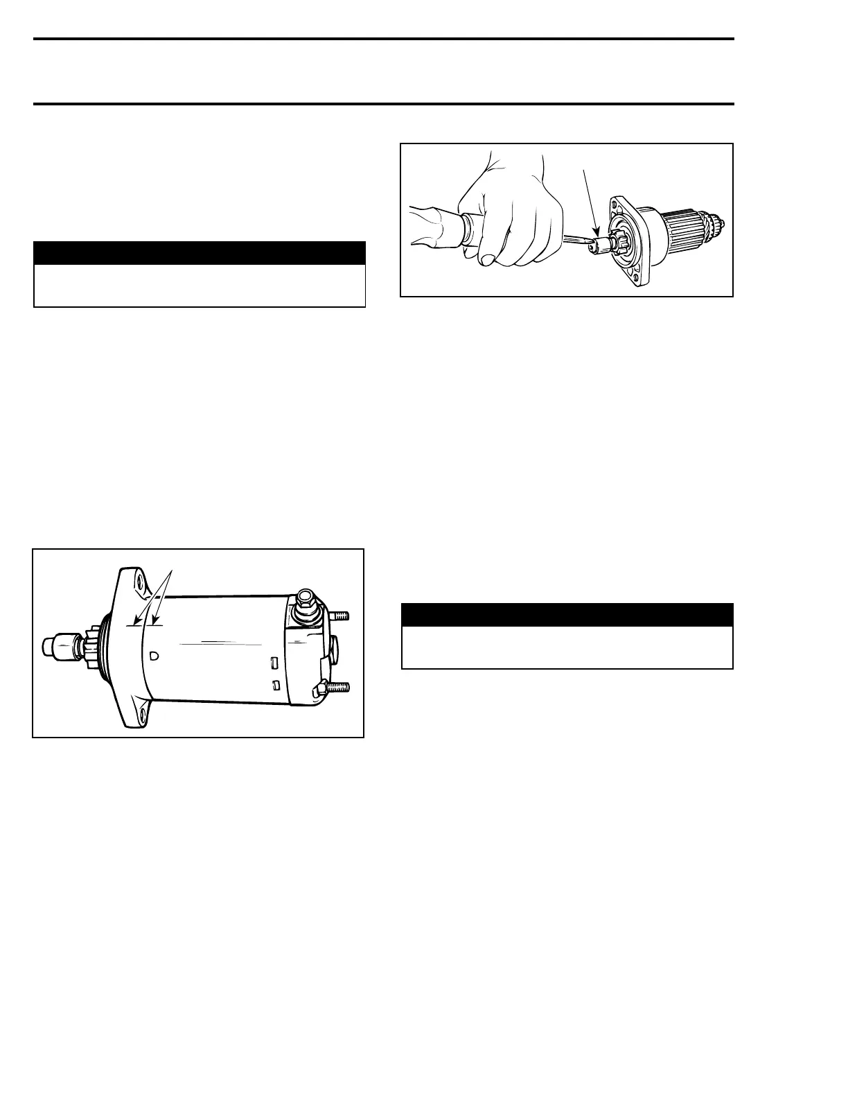
Tap the pinion stop collar no. 7 using a screw-
driver. Remove circlip no. 6. Disassemble pinion
stop collar no. 7 and spring no. 8.
A03E04A
1
1. Pinion stop collar
Turn clutch assembly no. 9 clockwise to remove
it from armature assembly no. 11.
Pull housing from armature.
CLEANING
Starter Parts
CAUTION: Yoke ass'y and drive unit assembly
must not be immersed in cleaning solvent.
Discard all O-rings.
Clean brushes and holders with a clean cloth
soaked in solvent. Brushes must be dried thor-
oughly with a clean cloth.
Blow brush holders clean using compressed air.
WARNING
Always wear safety glasses when using com-
pressed air.
Remove dirt, oil or grease from commutator using
acleanclothsoakedinsuitablesolvent. Drywell
using a clean, dry cloth.
Clean engine ring gear teeth and drive unit (clutch).
NOTE: Bushings or bearings must not be cleaned
with grease dissolving agents.
Immerse all metal components in cleaning solu-
tion. Dry using a clean, dry cloth.
INSPECTION
Armature
NOTE: An ohmmeter may be used for the follow-
ing testing procedures, except for the one con-
cerning shorted windings in armature.
190 smr2005-059