Section 10 STEERING SYSTEM
Subsection 01 (STEERING SYSTEM)
1
F18K0JA
2
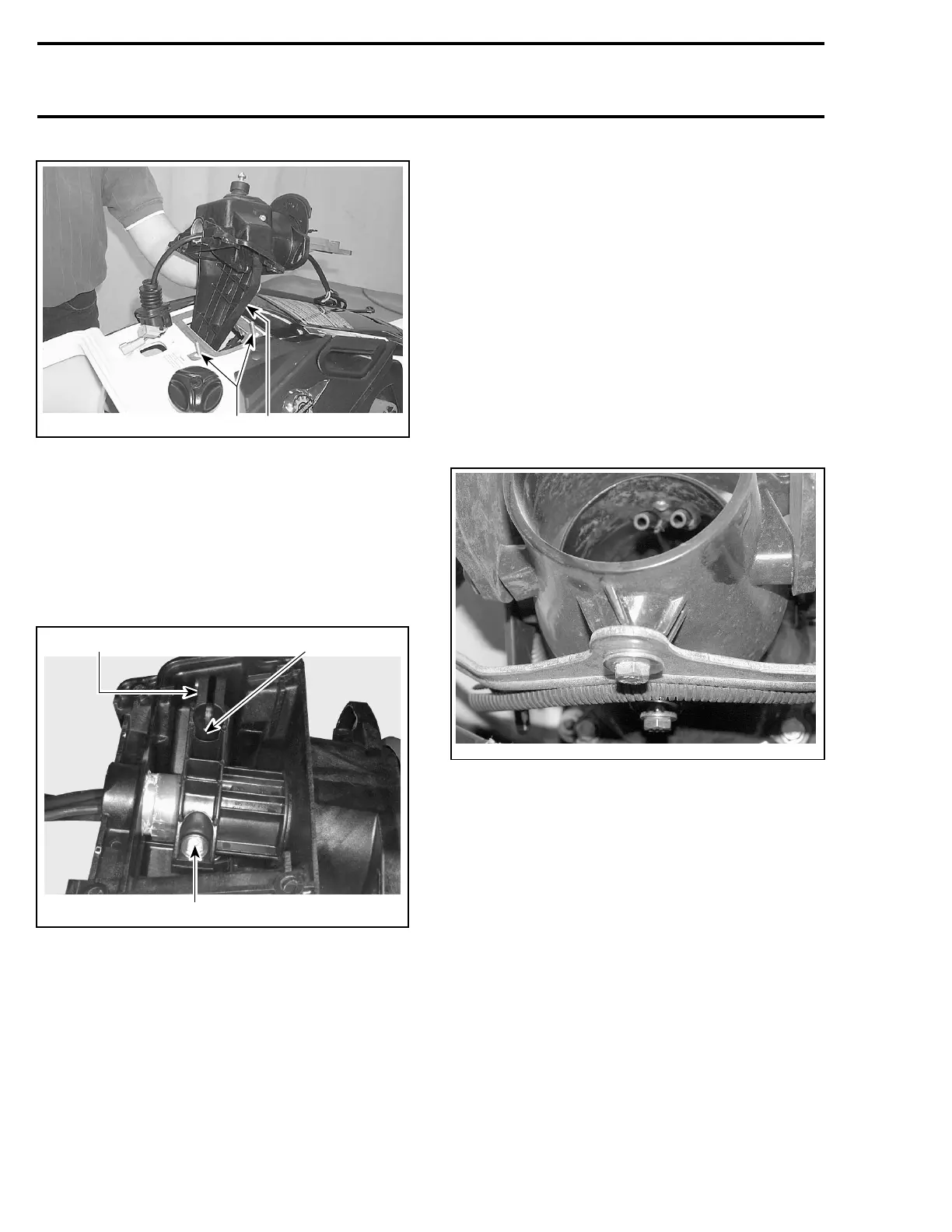
TYPICAL
1. Steering support
2. Retaining strip studs
Remove steering support no. 22 with handlebar,
wiring harnesses and cables.
Steering Stem Arm and Support
Loosen bolts no. 27 retaining steering stem arm
no. 24 to support no. 28.
F07K08A
21
2
1. Steering stem arm
2. Bolts
Remove steering stem arm and support.
Steering Cable
Disconnect steering cable no. 29 from steering
stem arm no. 24.
Remove retaining block no. 20.
Disconnect ball joint no. 30 from jet pump nozzle.
Remove ball joint no. 30 and jam nut no. 31 from
cable.
Loosen nut no. 32, then remove half rings no. 33
and O-ring no. 34.
NOTE: To loosen nut, use the steering cable tool
(P/N 295 000 145).
Remove steering cable from watercraft. Note its
routing for proper installation.
Nozzle
Disconnect steering cable from jet pump nozzle.
Remove:
– reverse gate, refer to REVERSE SYSTEM
–“U” lever bolt, located under nozzle
smr2005-062-003
– nozzle bolts retaining nozzle to venturi
– nozzle.
Remove nozzle.
ASSEMBLY
Assembly is essentially the reverse of disassem-
bly procedures. However, pay particular attention
to the following.
CAUTION: Apply all specified torques and ser-
vice products as per main illustration at the be-
ginning of this subsection.
Handle Grip and Grip Insert
When installing the grip insert no. 4 in the handle-
bar no. 5, ensure that it is properly inserted in the
slot at the end of the handlebar tubing.
282 smr2005-066