Section 10 STEERING SYSTEM
Subsection 01 (STEERING SYSTEM)
F02K0JA
1
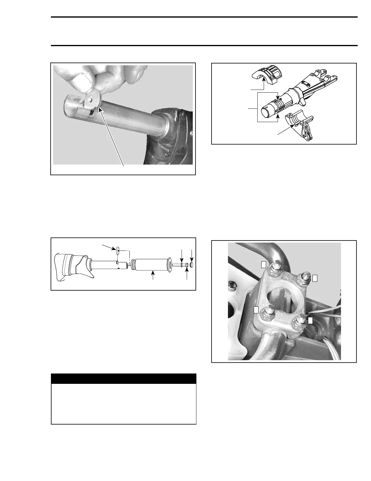
1. Grip insert
Install grip no. 1 on handlebar no. 5 matching it to
the notch in the handlebar.
Install flat washer and screw no. 3.
Torque screw to 7 N•m(62lbf•in).
Install cap no. 2.
F02K0KA
1
2
4
53
1. Grip insert
2. Grip
3. Flat washer
4. Screw. Torque to 7 N•m(62lbf•
in)
5. Cap
CAUTION: Ensure to install flat washer other-
wise screw will damage grip end.
Steering Stem Arm and Support
Position steering stem arm no. 24 and support
no. 28 onto steering stem.
WARNING
Make sure the integrated flat keys of the steer-
ing stem arm and support are properly seat-
ed in steering stem keyways. Steering stem
arm must be locked in place before torquing
the bolts.
F07K09A
2
1
2
1. Keyways
2. Integrated flat key
Replace lock nuts no. 35 by new ones.
Torque bolts no. 19 of steering stem arm to 6 N•m
(53 lbf•in).
Handlebar
Position handlebar no. 5. Install steering clamp
no. 18 and secure with new elastic stop nuts M8.
Torque nuts to 26 N•m(19lbf•ft) as per the fol-
lowing sequence.
F07K0VA
1
3
2
4
TORQUE SEQUENCE
Ball Joint
Secure the steering cable ball joint no. 30 to the
nozzle as per following illustrations.
CAUTION: Ensure the ball joint is parallel
(± 10°) to the nozzle arm.
smr2005-066 283